HP Integrity rx2620 Installation Guide, Third Edition - HP Integrity rx2620 (A - Page 54
Secure the Captive Screws, Step 13.
 |
View all HP Integrity rx2620 manuals
Add to My Manuals
Save this manual to your list of manuals |
Page 54 highlights
Installing Additional Components Installing an Additional Processor Step 13. Screw in the four processor captive screws, and the two heat sink captive screws. Refer to Figure 3-25 for the screw locations. Figure 3-25 Secure the Captive Screws 3 Front of server Processor torquing pattern 1 3 1 5 2 4 2 4 6 Step 14. Connect the processor power cable to the server power cable. Step 15. Connect the fan power cable to the system board. Step 16. Replace the processor airflow guide, and route the IDE and power cables as previously recorded. Step 17. Install the top metal cover, unless you are installing more components. See "Replacing the Top Metal Cover" on page 36. 54 Chapter 3
-
 1
1 -
2
-
3
-
4
-
5
-
6
-
7
-
8
-
9
-
10
-
11
-
12
-
13
-
14
-
15
-
16
-
17
-
18
-
19
-
20
-
21
-
22
-
23
-
24
-
25
-
26
-
27
-
28
-
29
-
30
-
31
-
32
-
33
-
34
-
35
-
36
-
37
-
38
-
39
-
40
-
41
-
42
-
43
-
44
-
45
-
46
-
47
-
48
-
 49
49 -
 50
50 -
 51
51 -
 52
52 -
 53
53 -
 54
54 -
 55
55 -
 56
56 -
 57
57 -
 58
58 -
 59
59 -
60
-
61
-
62
-
63
-
64
-
65
-
66
-
67
-
68
-
69
-
70
-
71
-
72
-
73
-
74
-
75
-
76
-
77
-
78
-
79
-
80
-
81
-
82
-
83
-
84
-
85
-
86
-
87
-
88
-
89
-
90
-
91
-
92
-
93
-
94
-
95
-
96
-
97
-
98
-
99
-
100
-
101
-
102
-
103
-
104
-
105
-
106
-
107
-
108
-
109
 |
 |

Chapter 3
Installing Additional Components
Installing an Additional Processor
54
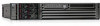
Step 13.
Screw in the four processor captive screws, and the two heat sink captive screws. Refer to
Figure 3-25 for the screw locations.
Figure 3-25 Secure the Captive Screws
Step 14.
Connect the processor power cable to the server power cable.
Step 15.
Connect the fan power cable to the system board.
Step 16.
Replace the processor airflow guide, and route the IDE and power cables as previously recorded.
Step 17.
Install the top metal cover, unless you are installing more components. See “Replacing the Top
Metal Cover” on page 36.
Front of server
Processor
torquing pattern
1
4
3
2
1
2
4
3
5
6