HP Integrity rx2620 Installation Guide, Third Edition - HP Integrity rx2620 (A - Page 52
Alignment Pins on Processor, Step 10.
 |
View all HP Integrity rx2620 manuals
Add to My Manuals
Save this manual to your list of manuals |
Page 52 highlights
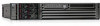
Installing Additional Components Installing an Additional Processor Step 10. Use the two alignment pins on the processor to properly align the processor on the system board. The two alignment pins fit in the alignment holes on the system board processor mount. The turbo fan power cable must be positioned so that it is located on the side of the heatsink that faces the front of the server. Figure 3-21 shows the alignment pins on the processor. Figure 3-21 Alignment Pins on Processor Front of server Alignment pins Figure 3-22 shows the alignment holes on the system board for the CPU 1 slot. Figure 3-22 Aligning the Processor Front of server Alignment holes 52 Chapter 3
-
 1
1 -
2
-
3
-
4
-
5
-
6
-
7
-
8
-
9
-
10
-
11
-
12
-
13
-
14
-
15
-
16
-
17
-
18
-
19
-
20
-
21
-
22
-
23
-
24
-
25
-
26
-
27
-
28
-
29
-
30
-
31
-
32
-
33
-
34
-
35
-
36
-
37
-
38
-
39
-
40
-
41
-
42
-
43
-
44
-
45
-
46
-
 47
47 -
 48
48 -
 49
49 -
 50
50 -
 51
51 -
 52
52 -
 53
53 -
 54
54 -
 55
55 -
 56
56 -
 57
57 -
58
-
59
-
60
-
61
-
62
-
63
-
64
-
65
-
66
-
67
-
68
-
69
-
70
-
71
-
72
-
73
-
74
-
75
-
76
-
77
-
78
-
79
-
80
-
81
-
82
-
83
-
84
-
85
-
86
-
87
-
88
-
89
-
90
-
91
-
92
-
93
-
94
-
95
-
96
-
97
-
98
-
99
-
100
-
101
-
102
-
103
-
104
-
105
-
106
-
107
-
108
-
109
 |
 |

Chapter 3
Installing Additional Components
Installing an Additional Processor
52
Step 10.
Use the two alignment pins on the processor to properly align the processor on the system board.
The two alignment pins fit in the alignment holes on the system board processor mount. The turbo
fan power cable must be positioned so that it is located on the side of the heatsink that faces the
front of the server. Figure 3-21 shows the alignment pins on the processor.
Figure 3-21 Alignment Pins on Processor
Figure 3-22 shows the alignment holes on the system board for the CPU 1 slot.
Figure 3-22 Aligning the Processor
Alignment pins
Front of server
Front of server
Alignment holes