IBM JS20 Hardware Maintenance Manual - Page 102
Closing, blade, server, cover, Input/output, connectors, devices
 |
UPC - 000435230263
View all IBM JS20 manuals
Add to My Manuals
Save this manual to your list of manuals |
Page 102 highlights
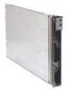
Closing the blade server cover Important: The blade server cannot be inserted into the BladeCenter unit until the cover is installed and closed. Do not attempt to override this protection. The following illustration shows how to close the blade server cover. Cover pins Complete the following steps to close the blade server cover: 1. Read the safety information beginning on page iii and "Installation guidelines" on page 71 2. If you removed the blade bezel assembly, replace it now. See "Installing the blade-server bezel assembly" on page 90 for instructions. 3. Lower the cover so that the slots at the rear slide down onto the pins at the rear of the blade server, as shown in the illustration. Before closing the cover, make sure that all components are installed and seated correctly and that you have not left loose tools or parts inside the blade server. 4. Pivot the cover to the closed position as shown in the illustration, until it clicks into place. Input/output connectors and devices The BladeCenter unit contains the input/output connectors that are available to the blade server. See the documentation that comes with the BladeCenter unit for information about the input/output connectors. The blade server does not support a direct connection to a monitor, keyboard, or mouse. Therefore, to enable communication between the blade server and these devices, you must perform the configuration tasks that are described in Chapter 3, "Configuration," on page 17 and the IBM BladeCenter and BladeCenter T Eserver Serial Over LAN Setup Guide. 92 BladeCenter JS20 Type 8842: Hardware Maintenance Manual and Troubleshooting Guide
-
 1
1 -
2
-
3
-
4
-
5
-
6
-
7
-
8
-
9
-
10
-
11
-
12
-
13
-
14
-
15
-
16
-
17
-
18
-
19
-
20
-
21
-
22
-
23
-
24
-
25
-
26
-
27
-
28
-
29
-
30
-
31
-
32
-
33
-
34
-
35
-
36
-
37
-
38
-
39
-
40
-
41
-
42
-
43
-
44
-
45
-
46
-
47
-
48
-
49
-
50
-
51
-
52
-
53
-
54
-
55
-
56
-
57
-
58
-
59
-
60
-
61
-
62
-
63
-
64
-
65
-
66
-
67
-
68
-
69
-
70
-
71
-
72
-
73
-
74
-
75
-
76
-
77
-
78
-
79
-
80
-
81
-
82
-
83
-
84
-
85
-
86
-
87
-
88
-
89
-
90
-
91
-
92
-
93
-
94
-
95
-
96
-
 97
97 -
 98
98 -
 99
99 -
 100
100 -
 101
101 -
 102
102 -
 103
103 -
 104
104 -
 105
105 -
 106
106 -
 107
107 -
108
-
109
-
110
-
111
-
112
-
113
-
114
-
115
-
116
-
117
-
118
-
119
-
120
-
121
-
122
-
123
-
124
-
125
-
126
-
127
-
128
-
129
-
130
-
131
-
132
-
133
-
134
-
135
-
136
-
137
-
138
-
139
-
140
-
141
-
142
-
143
-
144
-
145
-
146
-
147
-
148
-
149
-
150
-
151
-
152
-
153
-
154
-
155
-
156
-
157
-
158
-
159
-
160
-
161
-
162
-
163
-
164
-
165
-
166
-
167
-
168
-
169
-
170
-
171
-
172
-
173
-
174
-
175
-
176
-
177
-
178
-
179
-
180
-
181
-
182
-
183
-
184
-
185
-
186
-
187
-
188
-
189
-
190
-
191
-
192
-
193
-
194
-
195
-
196
-
197
-
198
-
199
-
200
-
201
-
202
-
203
-
204
-
205
-
206
-
207
-
208
-
209
-
210
-
211
-
212
-
213
-
214
-
215
-
216
-
217
-
218
 |
 |
