Icom IC-7800 Instruction Manual
Icom IC-7800 Manual
 |
View all Icom IC-7800 manuals
Add to My Manuals
Save this manual to your list of manuals |
Icom IC-7800 manual content summary:
- Icom IC-7800 | Instruction Manual - Page 1
THE TRANSCEIVER i7800 Instruction Manual A-6328H-1EX-u Printed in Japan © 2004-2006 Icom Inc. - Icom IC-7800 | Instruction Manual - Page 2
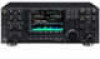
HF/50 MHz transceiver- IC-7800. The IC-7800 is designed and built with Icom's superior technology and craftsmanship. With proper care, this product should provide you with years of trouble-free operation. We would like to take a few moments of your time to thank you for making the IC-7800 your radio - Icom IC-7800 | Instruction Manual - Page 3
, set the transceiver's RF output power to less than the linear amplifier's maximum input level, otherwise, the linear amplifier will be damaged. Use Icom microphones only (supplied or optional). Other manufacturers' microphones have different pin assignments, and connection to the IC-7800 may - Icom IC-7800 | Instruction Manual - Page 4
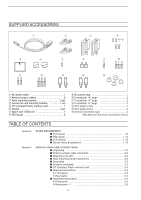
t y u i o !0 !1 !2 !3 !4 !5 q AC power cable 1 w Antenna jumper cables 2 e Rack mounting handles 1 pair r Screws for rack mounting handles 1 set t CF (Compact Flash) memory card 1 y Stands 1 pair u Spare fuse (FGB 2 A 1 i RCA plugs 2 o DC power plug 1 !0 2-conductor 1⁄8″ plugs - Icom IC-7800 | Instruction Manual - Page 5
2-7 D Connecting the IC-PW1/EURO 2-7 D Connecting a non-Icom linear amplifier 2-7 I band 3-4 D Using the band stacking registers 3-4 I Frequency setting 3-5 D Tuning with the main dial 3-5 D Direct Convenient functions for transmit 4-3 D About 5 MHz band operation (USA version only 4-3 I - Icom IC-7800 | Instruction Manual - Page 6
TABLE OF CONTENTS Section 5 D Memory keyer screen 4-8 D Editing a memory keyer 4-9 D Contest number set mode 4-10 D Keyer set mode 4-11 I Operating RTTY (FSK 4-13 D Convenient functions for receive 4-14 D About RTTY reverse mode 4-14 D Twin peak filter 4-14 D Functions for the RTTY decoder - Icom IC-7800 | Instruction Manual - Page 7
6-2 I Break-in function 6-3 D Semi break-in operation 6-3 D Full break-in operation 6-3 I ∂TX function 6-4 D ∂TX monitor function 6-4 I Monitor function 6-4 I Transmit filter width setting (SSB only 6-5 I Speech compressor (SSB only 6-5 I Split frequency operation 6-6 I Quick split function - Icom IC-7800 | Instruction Manual - Page 8
operation 11-4 Section 12 SET MODE I Set mode description 12-2 D Set mode operation 12-2 D Screen arrangement 12-3 I Level set mode 12-4 I ACC set mode 12-6 I Display set mode 12-11 I Miscellaneous (Others) set mode 12-14 I CF card set menu 12-22 D CF card set screen arrangement 12-22 - Icom IC-7800 | Instruction Manual - Page 9
TABLE OF CONTENTS D Load option set mode 12-24 I File saving 12-25 I File loading 12-26 I Changing the file name 12-27 I Deleting a file 12-28 I Formatting the CF card 12-28 Section 13 MAINTENANCE I Troubleshooting 13-2 D Transceiver power 13-2 D Transmit and receive 13-2 D Scanning 13 - Icom IC-7800 | Instruction Manual - Page 10
OF CONTENTS Section 16 UPDATING THE FIRMWARE I General 16-2 I Caution 16-2 I Preparation 16-3 D Firmware and firm utility 16-3 D File downloading 16-3 I Firmware update- CF memory card 16-4 I Firmware update- PC 16-6 D Connections 16-6 D IP address setting 16-7 D Updating from the PC 16 - Icom IC-7800 | Instruction Manual - Page 11
PANEL DESCRIPTION Section 1 I Front panel 1-2 I Rear panel 1-12 I LCD display 1-14 I Screen menu arrangement 1-15 1-1 - Icom IC-7800 | Instruction Manual - Page 12
transceiver is OFF when the internal power supply is switched ON. w TRANSMIT SWITCH [TRANSMIT] Selects transmitting or receiving. • The [TX manually when pushed for 1 sec. • The [TUNER] indicator blinks red during manual bug-key or straight key operation in keyer set mode. (p. 4-12) • A straight key - Icom IC-7800 | Instruction Manual - Page 13
set the microphone gain. Set the [MIC] control so that the ALC meter sometimes swings during normal voice transmission in SSB, AM or FM mode. Recommended level for an Icom of the transceiver's information and data. • The indicator beside the slot lights or blinks when the transceiver reads or - Icom IC-7800 | Instruction Manual - Page 14
MAIN band; p. 5-11) @2 AGC VOLUME SWITCH [AGC VR] (for SUB band; p. 5-11) ➥ Push to toggle [AGC] control usage ON and OFF. • Use [AGC] control to set the AGC time constant when switched ON. • The [AGC VR] indicator above this switch lights green when the control is ON. ➥ Turns the AGC function - Icom IC-7800 | Instruction Manual - Page 15
operation when pushed in FM mode. (pgs. 432, 4-33) ➥ Enters the tone set mode when pushed for 1 sec. in FM mode. (pgs. 4-32, 4-33) ➥ #0 TRANSMIT INDICATOR [TX] (for MAIN band) #1 TRANSMIT INDICATOR [TX] (for SUB band) Lights red while transmitting. • SUB band's [TX] indicator lights only - Icom IC-7800 | Instruction Manual - Page 16
used for FM, or non-pulse-type noise. • The [NB] indicator above this switch lights green while the function is activated. ➥ Enters blank-width set mode when pushed for 1 sec. $3 RECEIVE INDICATOR [RX] (for MAIN band) $4 RECEIVE INDICATOR [RX] (for SUB band) Lights green while receiving a signal and - Icom IC-7800 | Instruction Manual - Page 17
can be displayed with another screen, such as memory or set mode screen, simultaneously. %3 VOICE MEMORY RECORD SWITCH [REC] set mode screen display. ➥ Displays set mode menu screen when pushed for 1 sec. %6 TRANSMIT FREQUENCY CHECK SWITCH [XFC] (p. 6-6) Monitors the transmit frequency (including ∂TX - Icom IC-7800 | Instruction Manual - Page 18
memo pad capacity can be expanded from 5 to 10 in set mode. (p. 12-16) %8 VFO/MEMORY SWITCH [V/M] ➥ stacked frequencies in the band. (p. 3-4) • Icom's triple band stacking register memorizes 3 frequencies . (pgs. 3-5, 8-2) • e.g. to enter 14.195 MHz, push [F-INP] [1.8•1] [10•4] [GENE •] [1.8•1] [28 - Icom IC-7800 | Instruction Manual - Page 19
band; p. 5-19) ➥ Switches the notch function between auto, manual and OFF in SSB and AM modes. ➥ Turns the manual notch function ON and OFF when pushed in CW, RTTY and . (p. 12-15) • The quick split function can be turned OFF using set mode. (p. 12-15) ➥ Turns the split function ON and shifts the - Icom IC-7800 | Instruction Manual - Page 20
to decrease the frequency. The RIT or ∂TX functions must be ON. • The shift transceiver uses the DSP circuit for the PBT function. High cut Center Low cut *3 PBT CLEAR SWITCH [PBT CLEAR] (for MAIN band; p. 5-12) *4 PBT CLEAR SWITCH [PBT CLEAR] (for SUB band; p. 5-12) Clears the PBT settings - Icom IC-7800 | Instruction Manual - Page 21
the preselector is in use. *9 MANUAL NOTCH FILTER CONTROL [NOTCH] (for SUB band; outer control; p. 5-19) (0 MANUAL NOTCH FILTER CONTROL [NOTCH] (for depending on the quick RIT/∂TX clear function setting (p. 1217). (5 QUICK TUNING SWITCH [TS] (for MAIN band) (6 QUICK TUNING SWITCH [TS] (for SUB band) - Icom IC-7800 | Instruction Manual - Page 22
antenna with a PL-259 plug connector. t GROUND TERMINAL [GND] (p. 2-3) Connect this terminal to a ground to prevent electrical shocks, TVI, BCI and other problems. y CIRCUIT BREAKER Cuts off the AC input when over-current occurs. u RECEIVE ANTENNA B OUT [RX ANT B- OUT] i RECEIVE ANTENNA B IN [RX - Icom IC-7800 | Instruction Manual - Page 23
with another Icom CI-V transceiver or receiver. #1 RS-232C TERMINAL [RS-232C] (p. 2-5) Connects an RS-232C cable, D-sub 9-pin to connect the IC-7800 to a PC. Can be used for remotely control the IC-7800 without the optional CT-17, or for RTTY/PSK31 decoded signal output. The [RS-232C] interface is - Icom IC-7800 | Instruction Manual - Page 24
!2 IF FILTER INDICATOR Shows the selected IF filter number. !3 FREQUENCY READOUTS Shows the operating frequency. • Gray characters are used for non-active readout. !4 SELECT MEMORY CHANNEL INDICATOR (p. 9-7) Indicates the displayed memory channel is set as a select memory channel. !5 MEMORY CHANNEL - Icom IC-7800 | Instruction Manual - Page 25
the start up screen. Choose the desired screen using the following chart. Pushing [EXIT/SET] several times returns to the start up screen. See p. 12-3 for set mode arrangement. • PSK31 decoder screen (p. 4-21) • Spectrum scope screen (p. 5-2) • Memory channel screen (p. 8-3) • Voice recorder - Icom IC-7800 | Instruction Manual - Page 26
the IC-PW1 2-7 D Connecting a non-Icom linear amplifier 2-7 I Transverter jack information 2-8 I FSK and AFSK (SSTV) connections 2-8 I Microphone connector information 2-9 I Microphones (options 2-9 D SM-20 2-9 D HM-36 2-9 I Accessory connector information 2-10 CAUTION!: The transceiver - Icom IC-7800 | Instruction Manual - Page 27
of accessory equipment included with the IC-7800, see 'Supplied accessories' on p. iii of this manual. I Antenna jumper cable connection Connect TV sets, TV antenna elements, radios and other electromagnetic sources. The base of the transceiver has an adjustable stand for desktop use. Set the - Icom IC-7800 | Instruction Manual - Page 28
other problems, ground the transceiver through the coupling ring down. Strip the cable jacket and soft solder. 10 mm Soft solder 3⁄8 in 1-2 mm ≈ 1⁄16 in For radio communications, the antenna is of critical importance, transceiver and antenna. Low SWR allows full power for transmitting. The IC-7800 - Icom IC-7800 | Instruction Manual - Page 29
set mode. (p. 4-12) Microphones (p. 2-9) Optional SM-20 Optional HM-36 D Rear panel Antenna 1, 2, 3, 4 (p. 2-3) [Example]: ANT1 for 1.8-18 MHz bands, ANT 2 for 21-28 bands ANT3 for 50 MHz shocks, TVI and other problems. Straight key AC outlet R WARNING: Use the supplied AC power cable only. 2-4 - Icom IC-7800 | Instruction Manual - Page 30
[RS-232C] (p. 14-2) Used for computer control and transceive operation. The optional CT-17 is required when connecting a PC to [REMOTE]. [X-VERTER] Connects a transverter for V/UHF band use. [RELAY], [ALC] (p.2-7) Used for connecting a non-Icom - Icom IC-7800 | Instruction Manual - Page 31
output signal can be turned ON and OFF in set mode (p. 12-12) Keyboard Connects an USB connector (p. 16-6) Connects a PC via a LAN for the CPU firmware update. [METER] Connects an external meter, etc. MAIN band meter transmission and reception when switched ON during transceive operation, etc. 2-6 - Icom IC-7800 | Instruction Manual - Page 32
To an antenna ANT1 RELAY 50 Ω coaxial cable Transceiver ALC RF OUTPUT RF INPUT SEND ALC Non-Icom linear amplifier R WARNING: Set the transceiver output power and linear amplifier ALC output level referring to the linear amplifier instruction manual. The ALC input level must be in the range - Icom IC-7800 | Instruction Manual - Page 33
connecting to [ACC 1] • When using a PC application RTTY RTTY OUTPUT Connect to serial port, parallel 2 45 GND AF GND AUDIO INPUT port, speaker jack, microphone jack and line IN/OUT jack, etc. See the instruction manual of the PC 183 67 SEND PTT application for details. Rear panel view - Icom IC-7800 | Instruction Manual - Page 34
pin 1 for microphone operation. Take care when using a non-Icom microphone. I Microphones (options) D SM-20 q w e changes the frequency or memory channel number continuously. • While pushing [XFC switch can simulate a key paddle. Preset in the keyer set mode. (p. 4-12) w PTT SWITCH Push and hold to - Icom IC-7800 | Instruction Manual - Page 35
Tx) : Less than 200 mA Connected in parallel with ACC 2 pin 3. 4 MOD Modulator input. Connects to a modulator. Input impedance : 10 kΩ Input level : Approx. 100 mV rms 5 AF AF detector output. Fixed, regardless of [AF] position in default settings output. SPECIFICATIONS Output voltage - Icom IC-7800 | Instruction Manual - Page 36
3-2 I Main/Sub band selection 3-3 I Selecting VFO/memory mode 3-3 I Selecting an operating band 3-4 D Using the band stacking registers 3-4 I Frequency setting 3-5 D Tuning with the main dial 3-5 D Direct frequency entry with the keypad 3-5 D Quick tuning step 3-6 D Selecting "kHz" step - Icom IC-7800 | Instruction Manual - Page 37
[AF] : Max. counter- clockwise [RF] : Max. clockwise [MONI GAIN], [COMP], [DRIVE], [VOX GAIN], [ANTI VOX] : 12 o'clock After resetting the transceiver, set controls as shown in the figure below. [DELAY] [NR] : Max. clockwise : Max. counter clockwise [KEY SPEED] : 10-12 o'clock [NB] : Max - Icom IC-7800 | Instruction Manual - Page 38
band selection [MAIN] [SUB] 3 BASIC OPERATIONS The IC-7800 has 2 identical receivers, main and sub. The main VFO and memory modes. • "VFO" appears when in VFO mode, or the selected memory channel number appears when in memory mode. • Pushing [V/M] for 1 sec. transfers the contents of the selected - Icom IC-7800 | Instruction Manual - Page 39
and the default settings for each band. BAND 1.8 MHz 3.5 MHz 7 MHz 10 MHz 14 MHz 18 MHz 21 MHz 24 MHz 28 MHz 50 MHz General REGISTER 1 1.900000 MHz CW 3.550000 MHz LSB 7.050000 MHz LSB 10.120000 MHz CW 14.100000 MHz USB 18.100000 MHz USB 21.200000 MHz USB 24.950000 MHz USB 28.500000 MHz USB 50 - Icom IC-7800 | Instruction Manual - Page 40
3 BASIC OPERATIONS I Frequency setting D Tuning with the main dial Band keys Main dial Sub dial D Direct frequency entry with the keypad Keypad [EXAMPLE] 7.00000 MHz Push The transceiver has several tuning methods for convenient frequency tuning. q Push the desired band key on the keypad 1-3 times - Icom IC-7800 | Instruction Manual - Page 41
the quick tuning function ON and OFF. • "Z" appears when the quick tuning function ON. w Push [TS] for 1 sec. to enter tuning step setting display. • Selected tuning steps for all modes appear. e Select the desired operating mode. r Rotate the main dial to select the desired tuning step. t Repeat - Icom IC-7800 | Instruction Manual - Page 42
OFF. NOTE: 1 Hz tuning step activates for both main and sub bands simultaneously. Therefore, either [TS] can be used for the 1 Hz tuning step selection. D Auto tuning step function [F-1•Y][F-2•Z] [EXIT/SET] [F-7•SET] [F5•OTHERS] D Band edge warning beep When rotating main or sub dial rapidly, the - Icom IC-7800 | Instruction Manual - Page 43
AM, AM data, FM and FM data modes are available in the IC-7800. Select the desired operation mode as follows. To select a mode of USB is selected first when above 10 MHz; or LSB is selected first when below 10 MHz operation. (USB is selected when 5 MHz band is selected for the USA version.) - Icom IC-7800 | Instruction Manual - Page 44
increases I RF gain adjustment 3 BASIC OPERATIONS ➥ Rotate [AF] control clockwise to increase, counterclockwise to decrease the audio output level. • Set a suitable audio level. ➥ Rotate [RF] control clockwise to increase, counterclockwise to decrease the receiver sensitivity. [RF] for main [RF - Icom IC-7800 | Instruction Manual - Page 45
amplifier MOS-FETs. Indicates the drain terminal voltage of the final amplifier MOS-FETs. The IC-7800 can display the multi-function digital meter in the LCD display. This meter displays all ON. e Push [METER] for 1 sec., or push [EXIT/SET] to turn the multi-function digital meter OFF. 3-10 - Icom IC-7800 | Instruction Manual - Page 46
BASIC OPERATIONS A total of 3 meter types are available in the IC-7800- Standard, Edgewise and Bar meters. Follow the instructions below for the meter type selection. q Push [EXIT/SET] several times to return to normal screen, if necessary. w Push [F-7•SET], then push [F-3•DISPLAY] to select display - Icom IC-7800 | Instruction Manual - Page 47
3 BASIC OPERATIONS I Basic transmit operation D Transmitting [RF PWR] [TX] indicator [TRANSMIT] D Microphone gain adjustment [MIC] [METER] ALC to transmit. • The main band's [TX] indicator lights red. • When split operation is activated, the sub band's [TX] indicator lights. w Push [TRANSMIT] again - Icom IC-7800 | Instruction Manual - Page 48
D Drive gain adjustment [METER] [DRIVE] Drive gain range 5 9 +20 +40 1 +60dB 5 10 S 0 ID PO 0 10 SWR 10 COMP 50 1.5102 ALC ∞ 100 150 3 20 200 15 250 W A dB 44 52V VD 3 BASIC OPERATIONS The drive gain is active for all modes except SSB without speech compressor. The [DRIVE] - Icom IC-7800 | Instruction Manual - Page 49
for receive 4-2 D Convenient functions for transmit 4-3 D About 5 MHz band operation (USA version only 4-3 I Operating CW 4-4 D D Memory keyer screen 4-8 D Editing a memory keyer 4-9 D Contest number set mode 4-10 D Keyer set mode 4-11 I Operating RTTY (FSK 4-13 D Convenient functions - Icom IC-7800 | Instruction Manual - Page 50
MHz USB is automatically selected. e Rotate the main dial to tune a desired signal. • The S-meter indicates received signal strength when signal is received. r Rotate [AF] to set audio to a comfortable listening level. t Push [TRANSMIT] or [PTT] (microphone) to transmit. • [TX manual setting ON - Icom IC-7800 | Instruction Manual - Page 51
that you store these frequencies, mode and filter settings into memory channels for easy recall. *The FCC specifies center frequencies on the 5 MHz band. However, the IC-7800 displays carrier frequency. Therefore, tune the transceiver to 1.5 kHz below the specified FCC channel center frequency - Icom IC-7800 | Instruction Manual - Page 52
received. r Rotate [AF] to set audio to a comfortable listening level. t Push [TRANSMIT] to transmit. • [TX] indicator lights red. y Use AGC MID or AGC SLOW. ➥ Push [AGC VR] to turn the AGC time constant manual setting ON and OFF. • Rotate [AGC] control to adjust the time constant. • 1⁄4 function - Icom IC-7800 | Instruction Manual - Page 53
. • Adjustable within 300 to 900 Hz in 25 Hz steps. D CW side tone function [MONI GAIN] When the transceiver is in the receive condition (and the break-in function is OFF- p. 6-3) you can listen to the CW side practice CW sending. CW side tone level can be adjusted in level set mode (p. 12-5). 4-5 - Icom IC-7800 | Instruction Manual - Page 54
SEL] control when "APF" is selected for "DIGI-SEL VR Operation" in miscellaneous (others) set mode (p. 12-18). q During CW mode, push [APF/TPF] to turn the audio 137.8 kHz range, operation in CW mode is optionally available with the IC-7800. The RF signal from [X-VERTER] is used for the 137 kHz band - Icom IC-7800 | Instruction Manual - Page 55
I Electronic keyer functions [F-1]-[F-4] [CW] [EXIT/SET] 4 RECEIVE AND TRANSMIT The IC-7800 has a number of convenient functions for the built-in electronic keyer. q During CW mode, push [EXIT/SET] several times to normal screen, if necessary. w Push [F-3•KEYER] to select memory keyer screen. e - Icom IC-7800 | Instruction Manual - Page 56
mit, or set the break-in function ON (p. 6-3). e Push one of the function keys ([F-1•M1] to [F-4•M4]) to send the contents of the memory keyer. • Pushing a function key for 1 sec. repeatedly sends the contents; push any function key to cancel the transmission. • The contest serial number counter is - Icom IC-7800 | Instruction Manual - Page 57
CQ TEST CQ TEST DE ICOM ICOM TEST M2 UR 5NN✱ BK M3 CFM TU M4 QRZ? The contents of the memory keyer memories can be set using the memory keyer edit menu. The memory keyer can memorize and re-transmit 4 CW key codes for often-used CW sentences, contest serial numbers, etc. Total capacity of - Icom IC-7800 | Instruction Manual - Page 58
4 RECEIVE AND TRANSMIT D Contest number set mode [F-1•Y] [F-2•Z][F-4•DEF] [EXIT/SET] Main dial • Contest number set mode screen This menu is used to set the contest (serial) number and count up trigger, etc. • Setting contents q During CW mode operation, push [F-3•KEYER] to select memory keyer - Icom IC-7800 | Instruction Manual - Page 59
4 RECEIVE AND TRANSMIT D Keyer set mode [F-1•Y] [F-2•Z][F-4•DEF] [EXIT/SET] Main dial • Keyer set mode screen This set mode is used to set the memory keyer repeat time, dash weight, paddle specifications, keyer type, etc. • Setting contents q During CW mode operation, push [F-3•KEYER] to select - Icom IC-7800 | Instruction Manual - Page 60
[ELEC-KEY] connector on the front panel. • ELEC-KEY, BUG-KEY and Straight key can be selected. (default: ELEC-KEY) This item allows you to set the microphone [UP]/[DN] keys to be used as a paddle. • ON : [UP]/[DN] switches can be used for CW. • OFF : [UP]/[DN] switches cannot be - Icom IC-7800 | Instruction Manual - Page 61
IC-7800. When connecting a PC keyboard (p. 2-6), RTTY operation can be performed without an external RTTY terminal, TNC or PC. If you would rather use your RTTY terminal or TNC, consult the manual [F12] on the connected keyboard to transmit. • [TX] indicator lights red. y Type from the keyboard to - Icom IC-7800 | Instruction Manual - Page 62
11) ➥ Push [AGC] switch several times to select AGC FAST, AGC MID or AGC SLOW. ➥ Push [AGC VR] to turn the AGC time constant manual setting ON and OFF. • Rotate [AGC] control to adjust the time constant. • 1⁄4 function (p. 3-6) ➥ Push [1/4] to turn the 1⁄4 function ON and OFF. D About RTTY reverse - Icom IC-7800 | Instruction Manual - Page 63
Push [F-7•WIDE] to toggle the RTTY decode screen size from normal and wide. • S/RF meter type during wide screen indication can be selected in display set mode. (pgs. 3-11, 12-11) u Push [F-6•MAIN/SUB] to toggle the MAIN and SUB band for decode operation. • Dualwatch function (p. 5-16) should be ON - Icom IC-7800 | Instruction Manual - Page 64
the transmission. • No indication : Press [F12] on the keyboard to transmit the selected memory and press [F12] again to return to receive. t Push [EXIT/SET] to exit RTTY memory edit condition. NOTE: The transceiver always functions as the "AUTO TX/RX" setting when no keyboard is connected. 4-16 - Icom IC-7800 | Instruction Manual - Page 65
SK↵ RT6 CQ CQ CQ ↵CQ CQ CQ DE ICOM ICOM ICOM K↵ RT7 RIG&ANT ↵MY TRANSCEIVER IS IC-7800 & ANTENNA IS A 3-ELEMENT TRIBAND YAGI.↵ RT8 EQUIP. ↵MY RTTY EQUIPMENT IS INTERNAL FSK UNIT & DEMODULATOR OF THE IC-7800.↵ The contents of the RTTY memories can be set using the memory edit menu. The memory can - Icom IC-7800 | Instruction Manual - Page 66
OFF) Recommendation! If you use the FFT scope waveform for tuning, use the default or smaller number setting is recommended. Set the color for the FFT scope waveform. • The color is set in RGB format. • The set color is indicated in the box beside the RGB scale. • Push [F-3•Ω ≈] to select R (Red - Icom IC-7800 | Instruction Manual - Page 67
. • Push [F-3•Ω ≈] to select R (Red), G (Green) and B (Blue), and then rotate the main dial to set the ratio from 0 to 255. Set the text color in the TX buffer screen. • The color is set in RGB format. • The set color is indicated in the box beside the RGB scale. • Push [F-3•Ω ≈] to select R (Red - Icom IC-7800 | Instruction Manual - Page 68
name, if necessary. x Push [ABC], [123] or [Symbol] to select the character group, then rotate the main dial to select the character. • [ABC] : A to Z a character and push [F-4•SPACE] to insert a space. c Push [EXIT/SET] to set the file name. • File format z Push [F-5•OPTION] to enter save option - Icom IC-7800 | Instruction Manual - Page 69
IC-7800. When connecting a PC keyboard (p. 2-6), PSK31 operation can be performed without PSK software installed on your PC. If desired, you can also use your PSK software; consult the manual that comes with the software of the connected keyboard to transmit. • [TX] indicator lights red. y Type from - Icom IC-7800 | Instruction Manual - Page 70
. ➥ Push [AGC VR] to turn the AGC time constant manual setting ON and OFF. • Rotate [AGC] control to adjust the time constant. • Fine tuning (p. 3-7) ➥ During PSK, make sure that the kHz tuning step function is OFF (no "Z" indication), push [TS - Icom IC-7800 | Instruction Manual - Page 71
Push [F-7•WIDE] to toggle the PSK decode screen size from normal and wide. • S/RF meter type during wide screen indication can be selected in display set mode. (pgs. 3-11, 12-11) !0 Push [F-6•MAIN/SUB] to toggle the MAIN and SUB band for decode operation. • Dualwatch function (p. 5-16) should be ON - Icom IC-7800 | Instruction Manual - Page 72
. • No indication : Press [F12] on the keyboard to transmit the selected memory and press [F12] again to return to receive. t Push [EXIT/SET] to return to exit from PSK memory edit condition. NOTE: The transceiver always functions as the "AUTO TX/RX" setting when no keyboard is connected. 4-24 - Icom IC-7800 | Instruction Manual - Page 73
SK↵ PT6 CQ CQ CQ ↵CQ CQ CQ DE Icom Icom Icom K↵ PT7 RIG&ANT ↵My transceiver is IC-7800 & Antenna is a 3-element triband yagi.↵ PT8 EQUIP. ↵My PSK equipment is internal modulator & demodulator of the IC-7800.↵ The contents of the PSK memories can be set using the memory edit menu. The memory can - Icom IC-7800 | Instruction Manual - Page 74
) Recommendation! If you use the FFT scope waveform for tuning, using the default or smaller number setting is recommended. Set the color for the FFT scope waveform. • The color is set in RGB format. • The set color is indicated in the box beside the RGB scale. • Push [F-3•Ω ≈] to select R (Red - Icom IC-7800 | Instruction Manual - Page 75
. • Push [F-3•Ω ≈] to select R (Red), G (Green) and B (Blue), and then rotate the main dial to set the ratio from 0 to 255. Set the text color in the TX buffer screen. • The color is set in RGB format. • The set color is indicated in the box beside the RGB scale. • Push [F-3•Ω ≈] to select R (Red - Icom IC-7800 | Instruction Manual - Page 76
name, if necessary. x Push [ABC], [123] or [Symbol] to select the character group, then rotate the main dial to select the character. • [ABC] : A to Z a character and push [F-4•SPACE] to insert a space. c Push [EXIT/SET] to set the file name. • File format z Push [F-5•OPTION] to enter save option - Icom IC-7800 | Instruction Manual - Page 77
set audio to a comfortable listening level. t Push [TRANSMIT] or [PTT] (microphone) to transmit. • The TX . ➥ Push [AGC VR] to turn the AGC time constant manual setting ON and OFF. • Rotate [AGC] control to adjust the tion ON and OFF. • The transceiver automatically tunes the desired sig- nal within - Icom IC-7800 | Instruction Manual - Page 78
GAIN] to adjust the monitor gain. • Monitor indicator (above [MONI] switch) lights when the monitor function is ON. • Audio tone control (p. 12-4) ➥ Push [F-7•SET] then [F-1•LEVEL] to enter level set mode. Select an item with [F-1•Y]/[F-2•Z] then rotate the main dial to adjust the audio tone. 4-30 - Icom IC-7800 | Instruction Manual - Page 79
Rotate [AF] to set audio to a comfortable listening level. t Push [TRANSMIT] or [PTT] (microphone) to trans- mit. • The TX indicator lights red. the manual notch is ON. • Attenuator (p. 5-9) ➥ Push [ATT] several times to set the attenuator in 6 dB steps. • Pushing [ATT] for 1 sec. to set the - Icom IC-7800 | Instruction Manual - Page 80
set the repeater tone frequency in tone frequency set mode as described below. q Set the offset frequencies (HF, 50 MHz) and turn ON the quick split function in miscellaneous (others) set superimposed over your normal signal and must be set in advance. The transceiver has 50 tones from 67.0 Hz to - Icom IC-7800 | Instruction Manual - Page 81
subaudible tone. You can silently wait for calls from group members using the same tone. q Set the desired frequency band and select FM mode. w the S-indicator shows signal strength. • To open the squelch manually, push [XFC]. i Operate the transceiver in the normal way. o To cancel the tone squelch, - Icom IC-7800 | Instruction Manual - Page 82
your TNC and/or PC software, consult the manual that comes with the TNC and/or the software. q Connect a PC and TNC to the transceiver. (p. 2-8) w Push a sion as follows: • [COMP] : OFF • Tx bandwidth : MID • Tx Tone (Bass) : 0 • Tx Tone (Trebles): 0 ✔ For your information Carrier frequency - Icom IC-7800 | Instruction Manual - Page 83
I RIT function 5-10 D RIT monitor function 5-10 I AGC function 5-11 D Selecting the preset value 5-11 D Adjusting the AGC time constant 5-11 D Setting the AGC time constant preset value 5-11 I Twin PBT operation 5-12 I IF filter selection 5-13 D IF filter selection 5-13 D Filter passband - Icom IC-7800 | Instruction Manual - Page 84
fix mode. In addition, the IC-7800 has a mini scope screen to save screen space. D Center mode Displays signals around the set frequency within the selected span. The set frequency is always displayed at the in the internal scope circuit and do not indicate a transceiver malfunction. 5-2 - Icom IC-7800 | Instruction Manual - Page 85
the current spectrum waveform. • " HOLD " appears while the function is in use. • The peak hold function can be deactivated in scope set mode. i Push [EXIT/SET] to exit the scope screen. NOTE: If a strong signal is received, a ghost waveform may appear. Push [F-2•ATT] several times to activate - Icom IC-7800 | Instruction Manual - Page 86
main dial. • Push [F-4•DEF] for 1 sec. to select the default condition or value. • Push [F-3•Ω ≈] to select the set contents for some items. r Push [EXIT/SET] to exit from set mode. Turn the transmitting signal waveform indication ON and OFF. NOTE: The transmitting signal waveform indication is - Icom IC-7800 | Instruction Manual - Page 87
. Select the sweeping speed for the ±2.5 kHz span selection from SLOW, MID and FAST. NOTE: The waveform may be displayed incorrectly with "FAST" setting. Select the sweeping speed for the ±5 kHz span selection from SLOW, MID and FAST. NOTE: The waveform may be displayed incorrectly with "FAST - Icom IC-7800 | Instruction Manual - Page 88
FAST. Select the sweeping speed for the ±250 kHz span selection from SLOW, MID and FAST. Set the scope edge frequencies for fix mode scope with below 1.6 MHz band selection. • Set the frequencies within 0.030 to 1.600 MHz range in 1 kHz steps. Up to 500 kHz band width can be specified, so either - Icom IC-7800 | Instruction Manual - Page 89
between higher and lower frequencies become 5 to 500 kHz automatically while setting another edge frequency. Set the scope edge frequencies for fix mode scope when 11 to 15 MHz band is selected. • Set the frequencies within 11.000 to 15.000 MHz range in 1 kHz steps. Up to 500 kHz band width can - Icom IC-7800 | Instruction Manual - Page 90
between higher and lower frequencies become 5 to 500 kHz automatically while setting another edge frequency. Set the scope edge frequencies for fix mode scope when 30 to 45 MHz band is selected. • Set the frequencies within 30.000 to 45.000 MHz range in 1 kHz steps. Up to 500 kHz band width can - Icom IC-7800 | Instruction Manual - Page 91
all HF bands High-gain preamp for 24 MHz band and above ✔ About the "P.AMP2" The "P.AMP 2" is a high gain receive amplifier. When the "P.AMP 2" is used during times of strong electric fields, distortion sometimes results. In such cases, use the transceiver with the "P.AMP 1" or "P.AMP OFF" setting - Icom IC-7800 | Instruction Manual - Page 92
" and the shifting frequency appear when the function is ON. w Rotate the [RIT/∂TX] control. • Push [CLEAR] for 1 sec. to reset the RIT frequency. • Push [CLEAR] momentarily to reset the RIT frequency when the quick RIT/∂TX clear function is ON. (p. 12-18) • Push [RIT] for 1 sec. - Icom IC-7800 | Instruction Manual - Page 93
output level even when the received signal strength varies greatly. The transceiver has 3 preset AGC characteristics (time constant: fast, mid, slow • [AGC VR] indicator above the switch lights green. D Setting the AGC time constant preset value q Select the desired mode (not FM mode). w - Icom IC-7800 | Instruction Manual - Page 94
to slightly outside of the IF filter passband to reject interference. The IC-7800 uses DSP for the PBT function. Moving both [TWIN PBT] controls 25 or 50 Hz steps. • [TWIN PBT] should normally be set to the center positions (PBT setting is cleared) when there is no interference. • When PBT is used - Icom IC-7800 | Instruction Manual - Page 95
] for sub The transceiver has 3 passband width IF filters for each mode. For SSB, CW and PSK modes, the passband width can be set within 50 to 3600 and filter number is dis- played in the LCD. D Filter passband width setting (except FM mode) q Push [FILTER] for 1 sec. to enter filter set screen. - Icom IC-7800 | Instruction Manual - Page 96
filter shape from soft and sharp. r Push [EXIT•SET] to exit filter set screen. The filter shape can be set for each band (HF and 50 MHz bands), mode, as well as the passband width setting (CW only) independently as your default setting in filter shape set mode. The type of DSP filter shape for each - Icom IC-7800 | Instruction Manual - Page 97
or narrower. Select the filter shape for CW mode in HF bands. The set filter shape is automatically used only when the IF filter is set to 600 Hz or wider. Select the filter shape for SSB mode in 50 MHz band. The set filter shape is automatically used only when the IF filter is - Icom IC-7800 | Instruction Manual - Page 98
The IC-7800 has 2 independent receiver circuits so that you can use dualwatch with no compromises, even on different bands and modes. q Set the The RIT function can be used for the main readout only. • The ∂TX function can be used for the transmit readout (main readout when the split function OFF; - Icom IC-7800 | Instruction Manual - Page 99
I Noise blanker [NB] for main [NB] for sub [NB] control for main [NB] control for sub D NB set mode Set the noise attenuation level from 1 to 10. Set the noise pulse width from 1 to 100. 5 FUNCTIONS FOR RECEIVE The noise blanker eliminates pulse-type noise such as the noise from car ignitions. The - Icom IC-7800 | Instruction Manual - Page 100
to turn the noise reduction OFF. • [NR] indicator lights off. Deep rotation of the [NR] control results in audio signal masking or distortion. Set the [NR] control for maximum readability. I Dial lock function [LOCK] indicator for main [LOCK] indicator for sub [LOCK] for main [LOCK] for sub - Icom IC-7800 | Instruction Manual - Page 101
notch indication This transceiver has auto and manual notch functions. The auto notch function uses DSP to automatically attenuates more than 3 beat tones, tuning signals, etc., even if they are moving. The manual notch can be set to attenuate a frequency via the [NOTCH] control. The auto notch - Icom IC-7800 | Instruction Manual - Page 102
6-2 I Break-in function 6-3 D Semi break-in operation 6-3 D Full break-in operation 6-3 I ∂TX function 6-4 D ∂TX monitor function 6-4 I Monitor function 6-4 I Transmit filter width setting (SSB only 6-5 I Speech compressor (SSB only 6-5 I Split frequency operation 6-6 I Quick split function - Icom IC-7800 | Instruction Manual - Page 103
, rotate [ANTI VOX] to the point where the transceiver does not switch to transmit due to received audio from the speaker. t Adjust the VOX delay and the VOX voice delay in VOX set mode, if necessary. qPush [VOX/BK-IN] for 1 sec. to enter VOX set mode. w Select the desired item using [F-1•Y] or - Icom IC-7800 | Instruction Manual - Page 104
between transmit and receive when keying. The IC-7800 is capable for full break-in or semi break-in. During semi break-in operation, the transceiver selects transmit when keying, then automatically returns to receive after a pre-set time after you stop keying. q Push [CW] to select CW or CW - Icom IC-7800 | Instruction Manual - Page 105
the ∂TX shift frequency, push [∂TX] for 1 sec. The monitor function allows you to monitor your transmit IF signals in any mode. Use this to check voice characteristics while adjusting SSB transmit parameter. (p. 12-4) The CW sidetone functions regardless of the [MONI] switch setting. q Push - Icom IC-7800 | Instruction Manual - Page 106
filter functions regardless of the speech compressor use. • The following filters are specified as the default. Each of the filter width can be re-set in level set mode. (p. 12-5) WIDE : 100 Hz to 2.9 kHz MID : 300 Hz to 2.7 kHz NAR : 500 Hz to 2.5 kHz I Speech compressor (SSB only) [MIC] [METER - Icom IC-7800 | Instruction Manual - Page 107
for details. • The equalized transmit frequency and " " ap- pear on the LCD. • [SPLIT] indicator lights. • "TX" appears to show the transmit frequency readout. e Set the transmit frequency to 21.310 MHz in one of following ways. ➥ Rotate the main dial while pushing [XFC]. ➥ Rotate the sub - Icom IC-7800 | Instruction Manual - Page 108
not equalize the main and sub readout frequencies. q Suppose you are operating at 21.290 MHz (USB) in VFO mode. w Push [SPLIT] for 1 sec. • Split frequency The split lock function is ON by default, but can be turned OFF in set mode. (p. 12-15) q While split frequency operation is ON, push [LOCK - Icom IC-7800 | Instruction Manual - Page 109
message for transmit 7-6 D Recording 7-6 D Confirming a message for transmit 7-6 I Programming a memory name 7-7 I Sending a recorded message 7-8 D Transmit level setting 7-8 I Voice set mode 7-9 I Saving a voice memory into the CF card 7-10 D Saving the received audio memory 7-10 D Saving - Icom IC-7800 | Instruction Manual - Page 110
voice recorder [F-1] [F-2] [REC] [PLAY] [EXIT/SET] The IC-7800 has digital voice memories, up to 4 channels for transmit transmit channels. The transmit memory is very convenient for repeated CQ and number transmissions in contests, as well as when making consecutive calls during DX'peditions. q - Icom IC-7800 | Instruction Manual - Page 111
7 VOICE RECORDER FUNCTIONS I Recording a received audio D Basic recording [F-2•VOICE] [REC] [EXIT/SET] [F-7•T/R] D One-touch recording Up to 20 channels of receive voice memories are available in the IC-7800. And the total audio length of up to 209 sec. can be recorded in receive channels. However - Icom IC-7800 | Instruction Manual - Page 112
/SET] several times to close a multi-func- tion screen, if necessary. wPush [F-2•VOICE] to call up the voice recorder screen. • Previously selected screen, TX in the channel are played, or after 30 sec. y Push [EXIT/SET] twice to exit the voice recorder screen. Appear Counts down D One- - Icom IC-7800 | Instruction Manual - Page 113
memory. e Push [F-4•PROTECT] to turn the protect function ON and OFF. • " " indicator appears when the contents is protected. r Push [EXIT/SET] twice to exit the voice recorder screen. I Erasing the recorded contents [F-1•Y] [F-2•Z] [F-5•CLR] The recorded contents can be erased independently by - Icom IC-7800 | Instruction Manual - Page 114
recorder, record the desired message in advance as described below. The IC-7800 has digital voice memories for transmission, up to 4 channels and Adjust [MIC] control so that this indicator reads within 100%. q Push [EXIT/SET] several times to close a multi-func- tion screen, if necessary. wPush - Icom IC-7800 | Instruction Manual - Page 115
the desired character by rotating the main dial or by pushing the band key for number input. • Push [ABC] or [abc] to toggle capital and small letters. input a space. • Pushing the transceiver's keypad, [0]-[9], can also enter numerals. t Push [EXIT/SET] to input and set the name. • The cursor - Icom IC-7800 | Instruction Manual - Page 116
recorder screen as described as above. w Push [F-6•TX LEV.] to select the voice memory transmit level set condition. e Push the desired memory channel switch, [F-1•T1] to [F-4•T4], momentarily to transmit the contents. • The transceiver transmits automatically. •" " indicator appears and the - Icom IC-7800 | Instruction Manual - Page 117
. • ON : Monitors transmitting audio automatically when sending a recorded audio. • OFF : Monitors transmitting audio only when the monitor function is in use. Set the desired time period for the one-touch playing (when [PLAY] is pushed momentarily). • 3 to 10 sec. in 1 sec. steps can be - Icom IC-7800 | Instruction Manual - Page 118
Push [ABC], [123] or [Symbol] to select the character group, then rotate the main dial to select the character. • [ABC SPACE] to insert a space. c Push [EXIT/SET] to set the file name. • Saving location z Push screen automatically. D Saving the TX memory The TX memory contents can also be saved - Icom IC-7800 | Instruction Manual - Page 119
MEMORY OPERATION Section 8 I Memory channels 8-2 I Memory channel selection 8-2 D Using the [Y]/[Z] keys 8-2 D Using the keypad 8-2 I Memory list screen 8-3 D Selecting a memory channel using the memory list screen ...... 8-3 D Confirming programmed memory channels 8-3 I Memory channel - Icom IC-7800 | Instruction Manual - Page 120
8 MEMORY OPERATION I Memory channels The transceiver has 101 memory channels. Memory mode is etc. in memory mode. MEMORY CHANNEL Regular memory channels Scan edge memory channels MEMORY CHANNEL NUMBER 1-99 P1, P2 CAPABILITY TRANSFER TO VFO One frequency and one mode in each memory channel - Icom IC-7800 | Instruction Manual - Page 121
can select a desired memory channel from memory list screen. D Selecting a memory channel using the memory list screen [F-4•MEMORY] [Z] [Y] q Push [EXIT/SET] several times to close a multi-func- tion screen, if necessary. w Push [F-4•MEMORY] to select memory list screen. • [F-7•WIDE] switches the - Icom IC-7800 | Instruction Manual - Page 122
in VFO mode [Y] [Z] [MW] [EXAMPLE]: Programming 7.088 MHz/LSB into memory channel 12. q Set the desired frequency, operating mode and filter width in VFO memory channel is a blank channel (and does not have contents). w Set the desired frequency and operating mode in memory mode. • To program a - Icom IC-7800 | Instruction Manual - Page 123
EXAMPLE IN MEMORY MODE Operating frequency : 21.320 MHz/USB (M-ch 16) Contents of M-ch 16 : 14.018 MHz/CW Beep Beep Push for 1 sec. Beep Programmed in the selected memory channel: • Displayed frequency, mode and filter setting are transferred. • Programmed frequency and mode in the memory channel are - Icom IC-7800 | Instruction Manual - Page 124
desired character by rotating the main dial or by pushing the band key for number input. • Push [ABC] or [abc] to toggle capital and small letters input a space. • Pushing the transceiver's keypad, [0]-[9], can also enter numerals. y Push [EXIT/SET] to input and set the name. • The cursor disappears - Icom IC-7800 | Instruction Manual - Page 125
I Memo pads The transceiver has a memo pad function to store frequency and operating mode for easy write and recall. The memo pads are separate from memory channels. [MP-W] [MP-R] The default number of memo pads is 5, however, this can be increased to 10 in set mode if desired. (p. 1216 - Icom IC-7800 | Instruction Manual - Page 126
mode 9-3 I Programmed scan operation 9-4 I ∂F scan operation 9-4 I Fine programmed scan/∂F scan 9-5 I Memory scan operation 9-6 I Select memory scan operation 9-6 I Setting select memory channels 9-7 D Setting in scan screen 9-7 D Setting in memory list screen 9-7 D Erasing the select scan - Icom IC-7800 | Instruction Manual - Page 127
Scan speed can be selected from 2 levels, high or low, in scan set mode. See p. 9-3 for details. • Squelch condition SCAN STARTS WITH PROGRAMMED SCAN MEMORY SCAN SQUELCH OPEN The scan continues until it is stopped manually, and does not pause even if it detects signals. Scan pauses on each - Icom IC-7800 | Instruction Manual - Page 128
on unmodu- lated signals, regardless of whether the scan resume condition is set to ON or OFF. I Scan set mode [F-1•Y] [F-2•Z] [F-4•DEF] [EXIT/SET] Main dial When the squelch is open, scan continues until it is stopped manually- it does not pause on detected signals. When squelch is closed, scan - Icom IC-7800 | Instruction Manual - Page 129
cancel the scan, push [F-1•PROG]. • Rotating the main dial also cancels the scan. oPush [F-6•RECALL] for 1 sec. to recall the fre- quency that is set before starting the scan, if de- sired. If the same frequencies are programmed into the scan edge memory channel P1 and P2, programmed scan does - Icom IC-7800 | Instruction Manual - Page 130
or ∂F), the scan speed decreases when the squelch opens, but the transceiver keeps scanning. The scanning tuning step shifts from 50 Hz to 10 Hz when the squelch opens. [F-1•PROG] [F-2•∂F] [F-3•FINE] [EXIT/SET] q Push [EXIT/SET] several times to close a multi-func- tion screen, if necessary - Icom IC-7800 | Instruction Manual - Page 131
. w Select memory mode. e Push [F-5•SCAN] to select the scan screen. r Set the main band's [SQL] open or closed. • See page 9-2 for squelch condition. t Push [F-5•SEL No.] several times to select the se- lect scan number from #1, #2, #3 and #1/#2/#3. y Push [F-1•MEMO] to start the memory scan - Icom IC-7800 | Instruction Manual - Page 132
. y Repeat steps r to t to program another memory channel as a select memory channel, if desired. u Push [EXIT/SET] to exit the scan screen. D Setting in memory list screen q Push [EXIT/SET] several times to close a multi-func- tion screen, if necessary. w Push [F-4•MEMORY] to select memory list - Icom IC-7800 | Instruction Manual - Page 133
DEF] [F-6•T-SCAN] [F-1•Y] [F-2•Z] [EXIT/SET] The transceiver can detect subaudible tones in a received signal. By monitoring a signal that is being transmitted on a repeater input frequency, you can determine the tone frequency required to access the repeater. q Set the desired frequency or memory - Icom IC-7800 | Instruction Manual - Page 134
ANTENNA TUNER OPERATION Section 10 I Antenna connection and selection 10-2 I Antenna memory settings 10-3 D Antenna type selection 10-3 D Temporary memory 10-4 D Antenna selection mode 10-4 I Antenna tuner operation 10-5 D Tuner operation 10-5 D If the tuner cannot tune the antenna 10-6 10-1 - Icom IC-7800 | Instruction Manual - Page 135
10 ANTENNA TUNER OPERATION I Antenna connection and selection [ANT] The IC-7800 has 4 antenna connectors for the HF/50 MHz bands, [ANT1], [ANT2], [ANT3], and [ANT4]. For each operating band the IC-7800 covers, there is a band memory which can memorize a selected antenna. When you change the - Icom IC-7800 | Instruction Manual - Page 136
can be deactivated- deleting the antenna number from selection. This prevent the transceiver from accidentally transmitting into an empty antenna connector. In addition, a receive-only antenna can be specified for [ANT4]. q Select the antenna set screen as described above. w Push [F-7•ANT - Icom IC-7800 | Instruction Manual - Page 137
set screen. "#" appears when a different antenna from the original is selected. Push [F-4•TEMP-M] to turn the temporary memory ON and OFF. CAUTION!: Before transmitting with the manually selected antenna, make sure the selected antenna suits the operating frequency. Otherwise the transceiver - Icom IC-7800 | Instruction Manual - Page 138
operation D Tuner operation [TUNER] • MANUAL TUNING • AUTOMATIC TUNER START (HF bands only) The internal automatic antenna tuner matches the transceiver to the connected antenna automatically. After the when the SWR exceeds 1.5:1. This function is turned ON in set mode. (p. 12-15). 10-5 - Icom IC-7800 | Instruction Manual - Page 139
with the external antenna tuner, and turn OFF the IC-7800's tuner. After tuning is completed, turn the internal tuner ON. Otherwise, both tuners tune simultaneously and correct tuning may not be obtained. See the instruction manual included with each antenna tuner for their respective operations - Icom IC-7800 | Instruction Manual - Page 140
CLOCK AND TIMERS Section 11 I Time set mode 11-2 I Daily timer setting 11-3 I Setting sleep timer 11-4 I Timer operation 11-4 11-1 - Icom IC-7800 | Instruction Manual - Page 141
set mode [ABC]/[abc] [123]/[Symbol] [F-3•Ω ≈][F-5•EDIT]/[F-5•SET] [F-1•Y] [F-2•Z] [F-4•DEF] [EXIT/SET] Main dial The IC-7800 has a built-in calendar and 24-hour clock with daily power ON/OFF timer functions. Before operating these timer functions, set to select the character group, then rotate the - Icom IC-7800 | Instruction Manual - Page 142
the desired transceiver power OFF time. • When using power ON timer only, push [F-4•CLR] for 1 sec. to select "- - -." o Push [F-2•≈] to select the "MAIN" cell, then rotate the main dial to select the desired memory channel number in the main readout. • If using the currently set VFO condition in - Icom IC-7800 | Instruction Manual - Page 143
blinks. • Push [F-4•CLR] to select "- - -" to cancel the setting. t Push [F-7•SET] to set the time. • Push [EXIT/SET] to cancel the setting. • The timer indicator above [TIMER] switch lights green. y Push [EXIT/SET] to exit timer set screen. u The transceiver emits 10 beeps and turns OFF after the - Icom IC-7800 | Instruction Manual - Page 144
operation 12-2 D Screen arrangement 12-3 I Level set mode 12-4 I ACC set mode 12-6 I Display set mode 12-11 I Miscellaneous (Others) set mode 12-14 I CF card set menu 12-22 D CF card set screen arrangement 12-22 D Save option set mode 12-23 D Load option set mode 12-24 I File saving 12-25 - Icom IC-7800 | Instruction Manual - Page 145
for programming infrequently changed values or conditions of functions. The IC7800 has a level set mode, display set mode, timer set mode, accessory set mode, miscellaneous (others) set mode and CF card set mode. q Push [EXIT/SET] several times to close a multifunction screen, if necessary. w Push - Icom IC-7800 | Instruction Manual - Page 146
D Screen arrangement SET MODE 12 • Display set mode (p. 12-11) • Set mode menu screen (p. 12-2) • Time set mode (p. 11-2) • Level set mode (p. 12-4) • ACC set mode (p. 12-6) • Miscellaneous (Others) set mode (p. 12-14) • CF card set menu (p. 12-22) 12-3 - Icom IC-7800 | Instruction Manual - Page 147
of the transmit audio tone in AM mode from -5 to +5. (default: 0) Sets the treble level of the transmit audio tone in AM mode from -5 to +5. (default: 0) Sets the bass level of the transmit audio tone in FM mode from -5 to +5. (default: 0) Sets the treble level of the transmit audio tone in FM mode - Icom IC-7800 | Instruction Manual - Page 148
tone output level from 0 to 100% in 1% steps. (default: 50%) Turns the side tone output level limiting capability from ON and OFF. (default: ON) Sets the key-touch beep output level from 0 to 100% in 1% steps. (default: 50%) Turns the key-touch beep output level limiting capability from ON and - Icom IC-7800 | Instruction Manual - Page 149
• OFF : Outputs the main band's audio from the left, and sub band's audio from the right. (default) • ON : Outputs the mixed audio. I ACC set mode Selects the desired band for the audio and squelch signals output from [ACC1-A] (Audio: pin 5, Squelch: pin 6) from MAIN and SUB. • MAIN : Main band - Icom IC-7800 | Instruction Manual - Page 150
desired audio input level for modulation from [ACC1-B]. • Approx. 100 mV at 50% (default) setting. Sets the desired input level for modulation from [S/P DIF], within 0 to 100% in 1% steps. (default: 50%) Selects the desired connector(s) for modulation input when data mode - Icom IC-7800 | Instruction Manual - Page 151
12 SET MODE I ACC set mode (continued) Selects the desired connector(s) for modulation input when data 2 mode displayed in main readout. • SUB : Outputs the band signal displayed in sub readout. • TX : Outputs the band signal, that can be transmitted. (default) Selects the desired band for the - Icom IC-7800 | Instruction Manual - Page 152
transmit. • VD : Outputs the drain terminal voltage of the final amplifier MOS-FETs. • ID : Outputs the drain current of the final am- plifier MOS-FETs. Sets the output level for an external meter indication (main readout) with in 0 to 100% range in 1% steps. • Approx. 2.5 V at 50% (default - Icom IC-7800 | Instruction Manual - Page 153
12 SET MODE I ACC set mode (continued) Selects the transceiver's reference signal condition from IN, OFF and OUT. • IN : Use an external reference signal for the IC7800. • OFF : Not input/output the reference signal. (default) • OUT : Outputs the IC-7800 reference signal to externally connected - Icom IC-7800 | Instruction Manual - Page 154
Shadow (2), Shadow (3), Qubic (1), Qubic (2), Qubic (3), Qubic (4), IC-780 (1), IC-780 (2), IC-780 (3) and IC-780 (4). (default: Italic (1)) Selects the desired font for the displays other than frequency readout from Normal and Slim. (default: Normal) Set meter needle response from SLOW, MID and - Icom IC-7800 | Instruction Manual - Page 155
12 SET MODE I Display set mode (continued) Sets the memory name indication, during memory mode operation, ON and OFF. (default: ON) • ON : The programmed memory name is displayed above the frequency indication. • OFF : - Icom IC-7800 | Instruction Manual - Page 156
character blinks. x Push [ABC], [abc], [123] or [Symbol] to select the character group, then rotate the main dial to select the character. • Push [ABC] or [abc] to SPACE] to input a space. • Pushing the transceiver's keypad, [0]-[9], can also enter numerals. c Push [EXIT/SET] to set the name. 12-13 - Icom IC-7800 | Instruction Manual - Page 157
marker OFF after checking the frequency of the transceiver. A beep sounds each time a switch is pushed to confirm it. This function can be turned OFF for silent operation. (default: ON) The beep output level can be set in level set mode. (p. 12-5) A beep sounds when an operating frequency - Icom IC-7800 | Instruction Manual - Page 158
input the repeater offset for an HF band. The offset frequency can be set from -9.999 MHz to +9.999 MHz in 1 kHz steps. (default: -0.100 MHz) Sets the offset (difference between transmit and receive frequencies) for the quick split function. This setting is used for 50 MHz band FM mode only, and is - Icom IC-7800 | Instruction Manual - Page 159
operation ON. • Auto : The transceiver turns into transverter opera- tion condition when 2 to 13.8 V DC is applied to [ACC2-A/B] pin 6. Sets the desired offset frequency for the transverter operation within 0.000 to 99.999 MHz in 1 kHz steps. (default: 16.000 MHz) Selects the RTTY mark frequency - Icom IC-7800 | Instruction Manual - Page 160
I Miscellaneous (Others) set mode (continued) The IC-7800 speech processor has frequency, mode and signal level announcement. Signal level announcement can be deactivated if desired. (default: ON) When "OFF" is selected, the signal level is not announced. SET MODE 12 Selects the operating mode - Icom IC-7800 | Instruction Manual - Page 161
TX frequency clearing instruction with the [CLEAR] switch. • ON : Clears the RIT/∂TX frequency when [CLEAR] is pushed momentarily. • OFF : Clears the RIT/∂TX frequency when [CLEAR] is pushed for 1 sec. (default) Selects notch functions for SSB mode operation from Auto, Manual filter set screen - Icom IC-7800 | Instruction Manual - Page 162
to receive even when the operating mode is changed between SSB and CW. The frequency shifting value may differ according to the CW pitch setting. • ON : The displayed frequency shifts when the operating mode is changed between SSB and CW. • OFF : The displayed frequency does not shift. Selects the - Icom IC-7800 | Instruction Manual - Page 163
different address for each IC-7800; the range is 01h to 7Fh. Transceive operation is possible with the IC-7800 connected to other Icom HF transceivers or receivers. When rate) when "Decode" is selected in "RS-232C Function" above; settings are 300, 1200, 4800, 9600 and 19200 bps. (default: 9600) - Icom IC-7800 | Instruction Manual - Page 164
to your PC or LAN (Local Area Network) through the Ethernet connector. Turn the transceiver power OFF then ON to make the setting effective. See p. 16-7 for details. Sets subnet mask for the IC-7800 when connecting to your PC or LAN (Local Area Network) through the Ethernet connector. Turn - Icom IC-7800 | Instruction Manual - Page 165
12 SET MODE I CF card set menu D CF card set screen arrangement • CF card set menu • Format menu (p. 12-28) • Setting load screen (p. 12-26) • Setting save screen (p. 12-25) • Load option set mode (p. 12-24) • Firmware update (p. 16-4) • Save option set mode (p. 12-23) 12-22 - Icom IC-7800 | Instruction Manual - Page 166
contents and settings of miscellaneous (Other) set mode. • NO : Does not save. Selects the voice TX memory saving condition from YES and NO. (default: YES) • YES : Saves the voice TX memory. • : Saves the file in the current firmware version format being used. • Old Ver : Saves the file in the - Icom IC-7800 | Instruction Manual - Page 167
memory loading condition YES and NO. (default: YES). • YES : Loads and sets the voice TX memory. • NO : Use the original the voice TX memory. Selects the voice RX memory loading condition YES and NO. (default: NO). • YES : Loads and sets the voice RX memory. • NO : Use the original the voice RX - Icom IC-7800 | Instruction Manual - Page 168
SAVE] to select setting save screen. e Change the following conditions if desired. • File name: z Push [F-4•EDIT] to select file name edit condition. • Push [F-1• DIR/FILE] several times to select the file name, if necessary. x Push [ABC], [123] or [Symbol] to select the character group, then rotate - Icom IC-7800 | Instruction Manual - Page 169
24 for details. r Push [F-2•Y] or [F-3•Z] to select the desired setting file. t Push [F-4•LOAD]. • Confirmation screen appears. y Push [F-6•OK] to starts loading. • After the loading is completed, the message dialog, "Reboot the IC-7800," appears. u Turn the transceiver power OFF then ON to make the - Icom IC-7800 | Instruction Manual - Page 170
[F-3•Z] [EXIT/SET] [F-6•MAKE] The file name, saved in the CF card, can be re-named from the transceiver as desired. q During setting save screen name edit condition. t Push [ABC], [123] or [Symbol] to select the charac- ter group, then rotate the main dial to select the character. • [ABC] : A to Z ( - Icom IC-7800 | Instruction Manual - Page 171
the desired file to be deleted. r Push [F-5•REN/DEL] for 1 sec. • Confirmation screen appears. t Push [F-6•OK] to delete. • After the deleting, return to setting save screen automatically. A saved data in the CF memory card can be erased. IMPORTANT! Formatting erases all saved data in the CF memory - Icom IC-7800 | Instruction Manual - Page 172
MAINTENANCE Section 13 I Troubleshooting 13-2 D Transceiver power 13-2 D Transmit and receive 13-2 D Scanning 13-3 D Display and font selections 13-4 I Frequency calibration (approximate 13-5 I Opening the transceiver's case 13-6 I Clock backup battery replacement 13-6 I Fuse replacement 13 - Icom IC-7800 | Instruction Manual - Page 173
I Troubleshooting The following chart is designed to help you correct problems which are not equipment malfunctions. If you are unable to locate the cause of a problem or solve it through the use of this chart, contact you nearest Icom Dealer or Service Center. D Transceiver power PROBLEM - Icom IC-7800 | Instruction Manual - Page 174
. D Display PROBLEM POSSIBLE CAUSE The displayed frequency • The dial lock function is activated. does not change properly. • A set mode screen is I Voice synthesizer operation [SPEECH] for main [SPEECH] for sub The IC-7800 has built-in voice synthesizer to announce the frequency, mode, etc. - Icom IC-7800 | Instruction Manual - Page 175
of frequency readout indication fonts are available in the IC-7800. q Push [EXIT/SET] several times to close multi-function screen, if necessary. w Push [F-7•SET] to select set mode menu screen. e Push [F-3•DISP] to enter display set mode. r Push [F-1•Y] or [F-2•Z] to select "Display Type" item when - Icom IC-7800 | Instruction Manual - Page 176
the transceiver. However, a rough check may be performed by receiving radio station WWV, WWVH, or other standard frequency signals. CAUTION: The IC-7800 has been thoroughly adjusted and tested at the factory before being shipped. You should not have to re-calibrate it. [F-7•SET] [F-1•Y] [F-2•ACC - Icom IC-7800 | Instruction Manual - Page 177
transceiver is upside down. This may damage the transceiver. e Remove 7 screws from the bottom, and the 6 screws from the sides, then lift up the bottom cover. I Clock backup battery replacement The IC-7800 AC outlet before removing the transceiver's cover. q Remove the top cover as shown above. w - Icom IC-7800 | Instruction Manual - Page 178
the AC power cable from the AC outlet before removing the transceiver's cover. q Remove the bottom cover as shown left. w Replace the open fuse with a new sec. • The transceiver displays its initial VFO frequencies when resetting is complete. e Correct the set mode settings after resetting, if - Icom IC-7800 | Instruction Manual - Page 179
it will take longer to cool the transceiver. The power amplifier temperature can be monitored in the multi-function meter, TEMP gauge. I Screen saver function [F-4•DISPLAY] [F-7•SET] [F-1•Y] [F-2•ACC]/[F-2•Z] [EXIT/SET] Main dial [F-5•PREVIEW] The IC-7800 has a screen saver function to protect the - Icom IC-7800 | Instruction Manual - Page 180
contents 14-9 D Offset frequency setting 14-10 D Repeater tone/tone squelch frequency setting 14-10 D SSB transmission passband width setting 14-10 D Color setting 14-10 D Bandscope edge frequency setting 14-10 D Data mode with filter width setting 14-10 D Antenna memory setting 14-10 14-1 - Icom IC-7800 | Instruction Manual - Page 181
example IC-7800 BC-25 (optional) 9-15 V DC The transceiver can be connected through an optional CT-17 CI-V LEVEL CONVERTER to a PC equipped with an RS-232C port. The Icom Communications Interface-V (CI-V) controls of the transceiver. ct- 17 personal computer Up to 4 Icom CI-V transceivers or - Icom IC-7800 | Instruction Manual - Page 182
=±100 kHz; A6=±500 kHz; A7=±1 MHz) Set as non-select channel Set as select channel (1=#1; 2=#2; 3=#3; when no data command is specified, the previously set number or "#1" is selected) Set the number for select memory scan (0=ALL; 1=#1; 2=#2; 3=#3) Set scan resume OFF Set scan resume ON 00 Turn the - Icom IC-7800 | Instruction Manual - Page 183
Manual notch (0=OFF; 1=ON) 4C VSC (0=OFF; 1=ON) 4D Manual AGC (0=OFF; 1=ON) 4E DIGI-SEL (0=OFF; 1=ON) 4F Twin peak filter (0=OFF; 1=ON) 50 Dial lock (0=OFF; 1=ON) 19 00 Read the transceiver Send/read SSB TX Tone (Bass) level (0 =-5 to 10=+5) 050002 Send/read SSB TX Tone (Treble) - Icom IC-7800 | Instruction Manual - Page 184
(4), 14=IC-780 (1), 15=IC-780 (2), 16=IC-780 (3), 17=IC-780 (4)) MHz for HF (see p. 14-10 for details) Send/read FM split offset -9.999 to +9.999 MHz for 50 MHz (see p. 14-10 for details) Send/read split lock set (0=OFF, 1=ON) Send/read tuner auto start set (0=OFF, 1=ON) Send/read PTT tune set - Icom IC-7800 | Instruction Manual - Page 185
, 2=High) 050089 Send/read sub dial auto TS (0=OFF, 1=Low, 2=High) 050090 Send/read mic. up/down speed (0=Low, 1=High) 050091 Send/read quick RIT/∂TX clear function (0=OFF, 1=ON) 050092 Send/read SSB notch operation (0=Auto, 1=Manual, 2=Auto/Manual) 050093 Send/read AM notch operation - Icom IC-7800 | Instruction Manual - Page 186
15=15 sec.) 050136 Send/read contest number style (0=Normal, 1=190→ANO, MHz band (see p. 14-10 for details) Send/read antenna temporary memory set (0=OFF, 1=ON) Send/read antenna selection (0=OFF, 1=Manual, 2=Auto) Send/read usage for ANT2 (0=OFF, 1=TX/RX) Send/read usage for ANT3 (0=OFF, 1=TX - Icom IC-7800 | Instruction Manual - Page 187
read manual notch width (0=Wide, 1=Mid., 2=Nar.) 10 Send/read lock function set (0=OFF, 1=ON) 1B 00 Set/read repeater tone frequency (see p. 14-10 for details) 01 Set/read TSQL tone frequency (see p. 14-10 for details) 1C 00 Set/read the transceiver's condi- tion (0=Rx; 1=Tx) 01 Set - Icom IC-7800 | Instruction Manual - Page 188
, when sending/reading the oldest contents in the 21 MHz band, the code "0703" is used. • Frequency contest number (can be used for 1 channel only) D Codes for memory name, opening message and clock 2 name contents To send or read the desired memory name settings, the character codes, instructed - Icom IC-7800 | Instruction Manual - Page 189
kHz: 0-9 100 Hz: 0 (fixed) 100 kHz: 0-9 10 kHz: 0-9 10 MHz: 0-6 1 MHz: 0-9 1 kHz: 0-9 100 Hz: 0 (fixed) 100 kHz: 0-9 10 kHz: 0-9 10 MHz: 0-6 1 MHz: 0-9 *Not necessary when setting a frequency. D SSB transmission passband width setting The following data sequence is used when sending or reading the - Icom IC-7800 | Instruction Manual - Page 190
SPECIFICATIONS AND OPTIONS Section 15 I Specifications 15-2 D General 15-2 D Transmitter 15-2 D Receiver 15-3 D Antenna tuner 15-3 I Options 15-4 15-1 - Icom IC-7800 | Instruction Manual - Page 191
SPECIFICATIONS AND OPTIONS I Specifications D General • Frequency coverage (unit: MHz) Receiver Transmitter • Operating mode • Number side-band suppression • ∂TX variable range • Microphone connector HF bands) More than 70 dB (50 MHz band) : More than 63 dB (HF bands) More than 73 dB (50 MHz - Icom IC-7800 | Instruction Manual - Page 192
not indicate a transceiver malfunction. • 0.150 MHz • 10.490 MHz Sprious waveforms may be displayed on the spectrum scope screen regardless of the transceiver's condition (Tx or Rx). They are made in the scope circuit. This does not indicate a transceiver malfunction. All stated specifications are - Icom IC-7800 | Instruction Manual - Page 193
15 SPECIFICATIONS AND OPTIONS I Options • IC-PW1/EURO HF/50 MHz ALL BAND 1 kW LINEAR AMPLIFIER Full-duty-cycle 1 kW linear amplifier including an automatic antenna tuner. Has automatic tuning and band selection capability when used with an Icom transceiver. Full break-in (QSK) operation. The - Icom IC-7800 | Instruction Manual - Page 194
UPDATING THE FIRMWARE Section 16 I General 16-2 I Caution 16-2 I Preparation 16-3 D Firmware and firm utility 16-3 D File downloading 16-3 I Firmware update- CF memory card 16-4 I Firmware update- PC 16-6 D Connections 16-6 D IP address setting 16-7 D Updating from the PC 16-8 16-1 - Icom IC-7800 | Instruction Manual - Page 195
BASE-T/100 BASE TX compatible) is required when updating the firmware from the PC. Both memory card reader and Ethernet card/board are not supplied from Icom. Ask your PC dealer about a memory card reader and an Ethernet card/board for details. The IC-7800's firmware can be updated if desired. By - Icom IC-7800 | Instruction Manual - Page 196
directly. http://www.icom.co.jp/world/download/index.htm • No link is available from the top page. w Read "Regarding this Download Service" carefully, then click [AGREE]. e Click "IC-7800" link then click the firmware file link. r Type your name, call sign, IC-7800's serial number, etc., then click - Icom IC-7800 | Instruction Manual - Page 197
THE FIRMWARE I Firmware update- CF memory card When updating the firmware using with the CF memory card, no IP address as well as subnet mask settings are necessary. [F-3•FIRM UP]/[F-3•Z] [F-7•SET]/[F-7•CF CARD] /[F-7•CANCEL] q Copy the downloaded firmware data into the CF memory card ("IC-7800 - Icom IC-7800 | Instruction Manual - Page 198
[F-6•OK]. • Return to CF card set menu. !6 Push [POWER] to turn the IC-7800 power OFF, then ON again. !7 Depending on the updating, one to four dialog as at left appears in sequence. RWARNING!: NEVER turn the IC-7800 power OFF at this stage. The transceiver firmware will be damaged. !8 After the - Icom IC-7800 | Instruction Manual - Page 199
I Firmware update- PC D Connections Connect the IC-7800 and the PC through a LAN (Local Area Network) as follows. PC1 PC2 (192.168.100.11) (192.168.100.12) IC-7800 (192.168.100.13) Ethernet cable* (Patch cable) Hub/Router* to crossover port to WAN /Internet network • IP address setting - Icom IC-7800 | Instruction Manual - Page 200
D IP address setting [F-3 F-7•SET] 16 UPDATING THE FIRMWARE When updating the firmware from the CF memory card, the following settings are not necessary. IMPORTANT!: A fixed (static) IP address is used for the IC-7800. When you connect the IC-7800 to a LAN, ask the network manager about a usable/ - Icom IC-7800 | Instruction Manual - Page 201
). • Click [...], then select the file, as well as the location. t Type the IC-7800's IP address into "IC-7800 IP Address" text box. y Click [Start]. Type the IC-7800's IP address here. Click to start the firmware update u The window as at left appears. Read the precaution in the window carefully - Icom IC-7800 | Instruction Manual - Page 202
IC-7800 display. RWARNING!: NEVER turn the IC-7800 power OFF at this stage. The transceiver firmware will be damaged. Click [OK] to finish the firmware update. !0 Click [OK] to finish the firmware update. • The "FIRMWARE UPDATING" dialog as above disappears. !1 Push [POWER] to turn the IC-7800 - Icom IC-7800 | Instruction Manual - Page 203
a relative table shows a guideline for installation considerations. Below 30 MHz, the recommended limits are specified in terms of V/m or A/m of the IC-7800 which display the "CE" symbol on the serial number seal, comply with the essential requirements of the European Radio and Telecommunication - Icom IC-7800 | Instruction Manual - Page 204
Radio and Telecommunications Terminal Equipment Directive, 1999/5/EC, and that any applicable Essential Test Suite measurements have been performed. Kind of equipment: HF/50 MHz ALL MODE TRANSCEIVER Place and date of issue Icom (Europe) GmbH Himmelgeister straße 100 D-40225 Düsseldorf - Icom IC-7800 | Instruction Manual - Page 205
Please record the serial number of your IC-7800 transceiver below for future servicing reference: Serial Number : Date of purchase : Place where purchased : - Icom IC-7800 | Instruction Manual - Page 206
#08 (Spain) I GER I FRA I ESP I SWE I AUT I NED I POR I DEN I GBR I BEL I ITA I FIN I IRL I LUX I GRE I SUI I NOR IC-7800 #10 (United Kingdom) I GER I FRA I ESP I SWE I AUT I NED I POR I DEN I GBR I BEL I ITA I FIN I IRL I LUX I GRE I SUI I NOR
-
 1
1 -
 2
2 -
 3
3 -
 4
4 -
 5
5 -
 6
6 -
 7
7 -
8
-
9
-
10
-
11
-
12
-
13
-
14
-
15
-
16
-
17
-
18
-
19
-
20
-
21
-
22
-
23
-
24
-
25
-
26
-
27
-
28
-
29
-
30
-
31
-
32
-
33
-
34
-
35
-
36
-
37
-
38
-
39
-
40
-
41
-
42
-
43
-
44
-
45
-
46
-
47
-
48
-
49
-
50
-
51
-
52
-
53
-
54
-
55
-
56
-
57
-
58
-
59
-
60
-
61
-
62
-
63
-
64
-
65
-
66
-
67
-
68
-
69
-
70
-
71
-
72
-
73
-
74
-
75
-
76
-
77
-
78
-
79
-
80
-
81
-
82
-
83
-
84
-
85
-
86
-
87
-
88
-
89
-
90
-
91
-
92
-
93
-
94
-
95
-
96
-
97
-
98
-
99
-
100
-
101
-
102
-
103
-
104
-
105
-
106
-
107
-
108
-
109
-
110
-
111
-
112
-
113
-
114
-
115
-
116
-
117
-
118
-
119
-
120
-
121
-
122
-
123
-
124
-
125
-
126
-
127
-
128
-
129
-
130
-
131
-
132
-
133
-
134
-
135
-
136
-
137
-
138
-
139
-
140
-
141
-
142
-
143
-
144
-
145
-
146
-
147
-
148
-
149
-
150
-
151
-
152
-
153
-
154
-
155
-
156
-
157
-
158
-
159
-
160
-
161
-
162
-
163
-
164
-
165
-
166
-
167
-
168
-
169
-
170
-
171
-
172
-
173
-
174
-
175
-
176
-
177
-
178
-
179
-
180
-
181
-
182
-
183
-
184
-
185
-
186
-
187
-
188
-
189
-
190
-
191
-
192
-
193
-
194
-
195
-
196
-
197
-
198
-
199
-
200
-
201
-
202
-
203
-
204
-
205
-
206
 |
 |

THE TRANSCEIVER
i7800
Instruction Manual
A-6328H-1EX-
u
Printed in Japan
© 2004–2006 Icom Inc.