Icom IC-7800 Instruction Manual - Page 18
Audio Peak Filter/twin Peak Filter
 |
View all Icom IC-7800 manuals
Add to My Manuals
Save this manual to your list of manuals |
Page 18 highlights
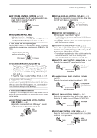
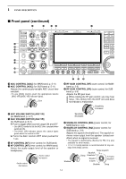
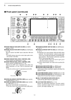
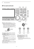
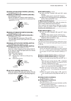
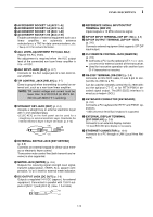
1 PANEL DESCRIPTION I Front panel (continued) %7 %8 %9 ^0 ^1 ^2 ^3 ^4 ^5 ^6 ^7 ^8 ^9 &0 &1&2 %7 MEMO PAD-WRITE SWITCH [MP-W] (p. 8-7) Programs the selected readout frequency and operating mode into a memo pad. • The 5 most recent entries remain in memo pads. • The memo pad capacity can be expanded from 5 to 10 in set mode. (p. 12-16) %8 VFO/MEMORY SWITCH [V/M] ➥ Switches the selected readout operating mode between the VFO and memory when pushed. (pgs. 3-3, 8-2) ➥ Transfers the memory contents to VFO when pushed for 1 sec. (p. 5-5) %9 KEYPAD ➥ Pushing a key selects the operating band. • [GENE•.] selects the general coverage band. ➥ Pushing the same key 2 or 3 times calls up other stacked frequencies in the band. (p. 3-4) • Icom's triple band stacking register memorizes 3 frequencies in each band. ➥ After pushing [F-INP•ENT], enters a frequency or memory channel. Pushing [F-INP•ENT] or [Y/[Z] is necessary to end. (pgs. 3-5, 8-2) • e.g. to enter 14.195 MHz, push [F-INP] [1.8•1] [10•4] [GENE •] [1.8•1] [28•9] [14•5] [F-INP•ENT]. ^0 MEMORY WRITE SWITCH [MW] (p. 8-4) Stores the selected readout frequency and operating mode into the displayed memory channel when pushed for 1 sec. • This function is available both in VFO and memory modes. &4 &5 &6 &8&3 &9 &7 ^1 MEMO PAD-READ SWITCH [MP-R] (p. 8-7) Each push calls up a frequency and operating mode in a memo pad. The 5 (or 10) most recently programmed frequencies and operating modes can be recalled, starting from the most recent. • The memo pad capacity can be expanded from 5 to 10 in set mode. (p. 12-16) ^2 FILTER SWITCH [FILTER] (for MAIN band; p. 5-13) ^3 FILTER SWITCH [FILTER] (for SUB band; p. 5-13) ➥ Selects one of 3 IF filter settings. ➥ Enters the filter set screen when pushed for 1 sec. ^4 AUDIO PEAK FILTER/TWIN PEAK FILTER SWITCH [APF/TPF] (for MAIN band) ^5 AUDIO PEAK FILTER/TWIN PEAK FILTER SWITCH [APF/TPF] (for SUB band) ➥ Push to turn the audio peak filter ON and OFF during CW mode operation. (p. 4-6) ➥ Push to turn the twin peak filter ON and OFF during RTTY mode operation. (p. 4-14) • " APF " appears when audio peak filter is in use. • " TPF " appears when twin peak filter is in use. ➥ During CW mode operation, push for 1 sec. to select the APF passband width from 80, 160 and 320 Hz. (p. 4-6) 1-8
-
 1
1 -
2
-
3
-
4
-
5
-
6
-
7
-
8
-
9
-
10
-
11
-
12
-
 13
13 -
 14
14 -
 15
15 -
 16
16 -
 17
17 -
 18
18 -
 19
19 -
 20
20 -
 21
21 -
 22
22 -
 23
23 -
24
-
25
-
26
-
27
-
28
-
29
-
30
-
31
-
32
-
33
-
34
-
35
-
36
-
37
-
38
-
39
-
40
-
41
-
42
-
43
-
44
-
45
-
46
-
47
-
48
-
49
-
50
-
51
-
52
-
53
-
54
-
55
-
56
-
57
-
58
-
59
-
60
-
61
-
62
-
63
-
64
-
65
-
66
-
67
-
68
-
69
-
70
-
71
-
72
-
73
-
74
-
75
-
76
-
77
-
78
-
79
-
80
-
81
-
82
-
83
-
84
-
85
-
86
-
87
-
88
-
89
-
90
-
91
-
92
-
93
-
94
-
95
-
96
-
97
-
98
-
99
-
100
-
101
-
102
-
103
-
104
-
105
-
106
-
107
-
108
-
109
-
110
-
111
-
112
-
113
-
114
-
115
-
116
-
117
-
118
-
119
-
120
-
121
-
122
-
123
-
124
-
125
-
126
-
127
-
128
-
129
-
130
-
131
-
132
-
133
-
134
-
135
-
136
-
137
-
138
-
139
-
140
-
141
-
142
-
143
-
144
-
145
-
146
-
147
-
148
-
149
-
150
-
151
-
152
-
153
-
154
-
155
-
156
-
157
-
158
-
159
-
160
-
161
-
162
-
163
-
164
-
165
-
166
-
167
-
168
-
169
-
170
-
171
-
172
-
173
-
174
-
175
-
176
-
177
-
178
-
179
-
180
-
181
-
182
-
183
-
184
-
185
-
186
-
187
-
188
-
189
-
190
-
191
-
192
-
193
-
194
-
195
-
196
-
197
-
198
-
199
-
200
-
201
-
202
-
203
-
204
-
205
-
206
 |
 |
