Icom IC-7800 Instruction Manual - Page 203
Installation Notes
 |
View all Icom IC-7800 manuals
Add to My Manuals
Save this manual to your list of manuals |
Page 203 highlights
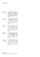
ABOUT CE INSTALLATION NOTES For amateur base station installations it is recommended that the forwards clearance in front of the antenna array is calculated relative to the EIRP (Effective Isotropic Radiated Power). The clearance height below the antenna array can be determined in most cases from the RF power at the antenna input terminals. Different exposure limits have been recommended for different frequencies, a relative table shows a guideline for installation considerations. Below 30 MHz, the recommended limits are specified in terms of V/m or A/m fields as they are likely to fall within the near-field region. Similarly, the antennas may be physically short in terms of electrical length and that the installation will require some antenna matching device which can create local, high intensity magnetic fields. Analysis of such installations is best considered in association with published guidance notes such as the FCC OET Bulletin 65 Edition 97-01 and its annexes relative to amateur transmitter installations. The EC recommended limits are almost identical to the FCC specified 'uncontrolled' limits and tables exist that show pre-calculated safe distances for different antenna types for different frequency bands. Further information can be found at http://www.arrl.org/. • Typical amateur radio installation Exposure distance assumes that the predominant radiation pattern is forward and that radiation vertically downward is at unity gain (sidelobe suppression is equal to main lobe gain). This is true of almost every gain antenna today. Exposed persons are assumed to be beneath the antenna array and have a typical height of 1.8 m. The figures assume the worst-case emission of constant carrier. For the bands 10 MHz and higher the following power density limits have been recommended: 10-144 MHz 2 W/sq m EIRP clearance heights by frequency band 1 Watts 2.1 m 10 Watts 2.8 m 25 Watts 3.4 m 100 Watts 5 m 1000 Watts 12 m Forward clearance, EIRP by frequency band 100 Watts 2 m 1000 Watts 6.5 m 10,000 Watts 20 m 100,000 Watts 65 m In all cases any possible risk depends on the transmitter being activated for long periods. (actual recommendation limits are specified as an average during 6 minutes) Normally the transmitter is not active for long periods of time. Some radio licenses will require that a timer circuit automatically cuts the transmitter after 1-2 minutes etc. Similarly some types of emission, i.e., SSB, CW, AM etc. have a lower 'average' output power and the assessed risk is even lower. Versions of the IC-7800 which display the "CE" symbol on the serial number seal, comply with the essential requirements of the European Radio and Telecommunication Terminal Directive 1999/5/EC. This warning symbol indicates that this equipment operates in non-harmonised frequency bands and/or may be subject to licensing conditions in the country of use. Be sure to check that you have the correct version of this radio or the correct programming of this radio, to comply with national licensing requirement.
-
 1
1 -
2
-
3
-
4
-
5
-
6
-
7
-
8
-
9
-
10
-
11
-
12
-
13
-
14
-
15
-
16
-
17
-
18
-
19
-
20
-
21
-
22
-
23
-
24
-
25
-
26
-
27
-
28
-
29
-
30
-
31
-
32
-
33
-
34
-
35
-
36
-
37
-
38
-
39
-
40
-
41
-
42
-
43
-
44
-
45
-
46
-
47
-
48
-
49
-
50
-
51
-
52
-
53
-
54
-
55
-
56
-
57
-
58
-
59
-
60
-
61
-
62
-
63
-
64
-
65
-
66
-
67
-
68
-
69
-
70
-
71
-
72
-
73
-
74
-
75
-
76
-
77
-
78
-
79
-
80
-
81
-
82
-
83
-
84
-
85
-
86
-
87
-
88
-
89
-
90
-
91
-
92
-
93
-
94
-
95
-
96
-
97
-
98
-
99
-
100
-
101
-
102
-
103
-
104
-
105
-
106
-
107
-
108
-
109
-
110
-
111
-
112
-
113
-
114
-
115
-
116
-
117
-
118
-
119
-
120
-
121
-
122
-
123
-
124
-
125
-
126
-
127
-
128
-
129
-
130
-
131
-
132
-
133
-
134
-
135
-
136
-
137
-
138
-
139
-
140
-
141
-
142
-
143
-
144
-
145
-
146
-
147
-
148
-
149
-
150
-
151
-
152
-
153
-
154
-
155
-
156
-
157
-
158
-
159
-
160
-
161
-
162
-
163
-
164
-
165
-
166
-
167
-
168
-
169
-
170
-
171
-
172
-
173
-
174
-
175
-
176
-
177
-
178
-
179
-
180
-
181
-
182
-
183
-
184
-
185
-
186
-
187
-
188
-
189
-
190
-
191
-
192
-
193
-
194
-
195
-
196
-
197
-
 198
198 -
 199
199 -
 200
200 -
 201
201 -
 202
202 -
 203
203 -
 204
204 -
 205
205 -
 206
206
 |
 |