Icom IC-7800 Instruction Manual - Page 45
Meter indication selection
 |
View all Icom IC-7800 manuals
Add to My Manuals
Save this manual to your list of manuals |
Page 45 highlights
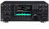
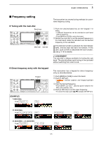
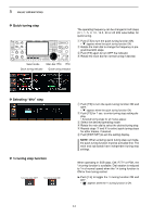
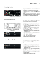
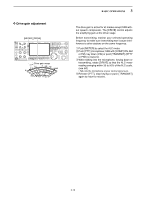
3 BASIC OPERATIONS I Meter indication selection [METER] Signal strength level readout 5 1 9 +20 +40 +60dB 5 10 S ID readout Power level readout VSWR readout 0 ID PO 0 10 SWR 10 COMP 50 1.5102 ALC ∞ 100 150 3 20 200 15 250 W A dB 44 52V VD Compression level readout ALC level readout VD readout D Multi-function digital meter "P-HOLD" indicator The S/RF meter indication, during transmit, can be selected from the following items as you desire. ➥ Push [METER] several times to select the desired item. Indicates the RF output power in watts. Indicates the VSWR on the transmission line. Indicates the ALC level. The ALC circuit begins to activate when the RF output power reaches a preset level. Indicates the compression level when the speech compressor is in use. Indicates the drain current of the final amplifier MOS-FETs. Indicates the drain terminal voltage of the final amplifier MOS-FETs. The IC-7800 can display the multi-function digital meter in the LCD display. This meter displays all transmit parameters simultaneously. q Push [METER] for 1 sec. to turn the multi-function digital meter ON. w Push [F-1•P-HOLD] to toggle the peak level hold function ON. • "P-HOLD" appears on the window title when the peak level hold function is ON. e Push [METER] for 1 sec., or push [EXIT/SET] to turn the multi-function digital meter OFF. 3-10
-
 1
1 -
2
-
3
-
4
-
5
-
6
-
7
-
8
-
9
-
10
-
11
-
12
-
13
-
14
-
15
-
16
-
17
-
18
-
19
-
20
-
21
-
22
-
23
-
24
-
25
-
26
-
27
-
28
-
29
-
30
-
31
-
32
-
33
-
34
-
35
-
36
-
37
-
38
-
39
-
 40
40 -
 41
41 -
 42
42 -
 43
43 -
 44
44 -
 45
45 -
 46
46 -
 47
47 -
 48
48 -
 49
49 -
 50
50 -
51
-
52
-
53
-
54
-
55
-
56
-
57
-
58
-
59
-
60
-
61
-
62
-
63
-
64
-
65
-
66
-
67
-
68
-
69
-
70
-
71
-
72
-
73
-
74
-
75
-
76
-
77
-
78
-
79
-
80
-
81
-
82
-
83
-
84
-
85
-
86
-
87
-
88
-
89
-
90
-
91
-
92
-
93
-
94
-
95
-
96
-
97
-
98
-
99
-
100
-
101
-
102
-
103
-
104
-
105
-
106
-
107
-
108
-
109
-
110
-
111
-
112
-
113
-
114
-
115
-
116
-
117
-
118
-
119
-
120
-
121
-
122
-
123
-
124
-
125
-
126
-
127
-
128
-
129
-
130
-
131
-
132
-
133
-
134
-
135
-
136
-
137
-
138
-
139
-
140
-
141
-
142
-
143
-
144
-
145
-
146
-
147
-
148
-
149
-
150
-
151
-
152
-
153
-
154
-
155
-
156
-
157
-
158
-
159
-
160
-
161
-
162
-
163
-
164
-
165
-
166
-
167
-
168
-
169
-
170
-
171
-
172
-
173
-
174
-
175
-
176
-
177
-
178
-
179
-
180
-
181
-
182
-
183
-
184
-
185
-
186
-
187
-
188
-
189
-
190
-
191
-
192
-
193
-
194
-
195
-
196
-
197
-
198
-
199
-
200
-
201
-
202
-
203
-
204
-
205
-
206
 |
 |