Icom IC-7800 Instruction Manual - Page 181
Remote jack CI-V information
 |
View all Icom IC-7800 manuals
Add to My Manuals
Save this manual to your list of manuals |
Page 181 highlights
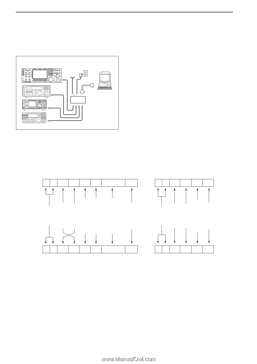
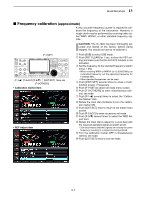
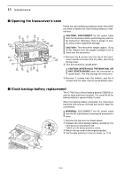
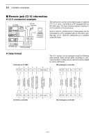
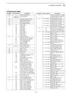
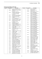
14 CONTROL COMMAND I Remote jack (CI-V) information D CI-V connection example IC-7800 BC-25 (optional) 9-15 V DC The transceiver can be connected through an optional CT-17 CI-V LEVEL CONVERTER to a PC equipped with an RS-232C port. The Icom Communications Interface-V (CI-V) controls of the transceiver. ct- 17 personal computer Up to 4 Icom CI-V transceivers or transceivers can be connected to a PC equipped with an RS-232C port. See pgs. 12-19, 12-20 for setting the CI-V condition using set mode. mini-plug cable D Data format Controller to IC-7800 q w ert FE FE 6A E0 Cn Sc y Data area The CI-V system can be operated using the following data formats. Data formats differ according to command numbers. A data area or sub command is added for some commands. OK message to controller u FD FE FE E0 6A FB FD End of message code (fixed) (fixed) NG code OK code Transceiver's default address Controller's default address Preamble code (fixed) Preamble code (fixed) Transceiver's default address Controller's default address Command number (see the command table) Sub command number (see command table) BCD code data for frequency or memory number entry End of message code (fixed) (fixed) FE FE E0 6A Cn Sc Data area FD q w ert y u IC-7800 to controller FE FE E0 6A FA FD NG message to controller 14-2
-
 1
1 -
2
-
3
-
4
-
5
-
6
-
7
-
8
-
9
-
10
-
11
-
12
-
13
-
14
-
15
-
16
-
17
-
18
-
19
-
20
-
21
-
22
-
23
-
24
-
25
-
26
-
27
-
28
-
29
-
30
-
31
-
32
-
33
-
34
-
35
-
36
-
37
-
38
-
39
-
40
-
41
-
42
-
43
-
44
-
45
-
46
-
47
-
48
-
49
-
50
-
51
-
52
-
53
-
54
-
55
-
56
-
57
-
58
-
59
-
60
-
61
-
62
-
63
-
64
-
65
-
66
-
67
-
68
-
69
-
70
-
71
-
72
-
73
-
74
-
75
-
76
-
77
-
78
-
79
-
80
-
81
-
82
-
83
-
84
-
85
-
86
-
87
-
88
-
89
-
90
-
91
-
92
-
93
-
94
-
95
-
96
-
97
-
98
-
99
-
100
-
101
-
102
-
103
-
104
-
105
-
106
-
107
-
108
-
109
-
110
-
111
-
112
-
113
-
114
-
115
-
116
-
117
-
118
-
119
-
120
-
121
-
122
-
123
-
124
-
125
-
126
-
127
-
128
-
129
-
130
-
131
-
132
-
133
-
134
-
135
-
136
-
137
-
138
-
139
-
140
-
141
-
142
-
143
-
144
-
145
-
146
-
147
-
148
-
149
-
150
-
151
-
152
-
153
-
154
-
155
-
156
-
157
-
158
-
159
-
160
-
161
-
162
-
163
-
164
-
165
-
166
-
167
-
168
-
169
-
170
-
171
-
172
-
173
-
174
-
175
-
 176
176 -
 177
177 -
 178
178 -
 179
179 -
 180
180 -
 181
181 -
 182
182 -
 183
183 -
 184
184 -
 185
185 -
 186
186 -
187
-
188
-
189
-
190
-
191
-
192
-
193
-
194
-
195
-
196
-
197
-
198
-
199
-
200
-
201
-
202
-
203
-
204
-
205
-
206
 |
 |