Icom IC-7800 Instruction Manual - Page 20
Tx Control [rit, Passband Tuning Controls [twin Pbt], Pbt Clear Switch [pbt Clear]
 |
View all Icom IC-7800 manuals
Add to My Manuals
Save this manual to your list of manuals |
Page 20 highlights
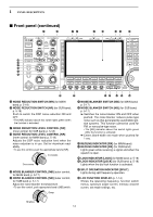
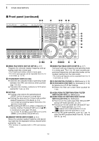
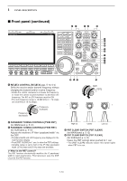
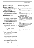
1 PANEL DESCRIPTION I Front panel (continued) *0 *1 *3 *4 *2 *5 *7 *8 *6 *9 (0 (1 (2 (3 (4 *0 RIT/∂TX CONTROL [RIT/∂TX] (pgs. 5-10, 6-4) Shifts the receive and/or transmit frequency without changing the transmit and/or receive frequency. • Rotate the control clockwise to increase the frequency, or rotate the control counterclockwise to decrease the frequency. The RIT or ∂TX functions must be ON. • The shift frequency range is ±9.999 kHz in 1 Hz steps (or ±9.99 kHz in 10 Hz steps). Frequency decreases Frequency increases (5 (6 (7 - (8 PBT1 PBT2 + *1 PASSBAND TUNING CONTROLS [TWIN PBT] (for MAIN band; p. 5-12) *2 PASSBAND TUNING CONTROLS [TWIN PBT] (for SUB band; p. 5-12) Adjusts the receiver's IF filter "passband width" via the DSP. • Passband width and shift frequency are displayed in the multi-function display. • Push [PBT CLEAR] for 1 sec. to clear the PBT settings. • Variable range is set to half of the IF filter passband width. 25 Hz steps and 50 Hz steps are available. ✔ What is the PBT control? The PBT function electronically modifies the IF passband width to reject interference. This transceiver uses the DSP circuit for the PBT function. High cut Center Low cut *3 PBT CLEAR SWITCH [PBT CLEAR] (for MAIN band; p. 5-12) *4 PBT CLEAR SWITCH [PBT CLEAR] (for SUB band; p. 5-12) Clears the PBT settings when pushed for 1 sec. • The [PBT CLEAR] indicator above this switch lights when PBT is in use. 1-10
-
 1
1 -
2
-
3
-
4
-
5
-
6
-
7
-
8
-
9
-
10
-
11
-
12
-
13
-
14
-
 15
15 -
 16
16 -
 17
17 -
 18
18 -
 19
19 -
 20
20 -
 21
21 -
 22
22 -
 23
23 -
 24
24 -
 25
25 -
26
-
27
-
28
-
29
-
30
-
31
-
32
-
33
-
34
-
35
-
36
-
37
-
38
-
39
-
40
-
41
-
42
-
43
-
44
-
45
-
46
-
47
-
48
-
49
-
50
-
51
-
52
-
53
-
54
-
55
-
56
-
57
-
58
-
59
-
60
-
61
-
62
-
63
-
64
-
65
-
66
-
67
-
68
-
69
-
70
-
71
-
72
-
73
-
74
-
75
-
76
-
77
-
78
-
79
-
80
-
81
-
82
-
83
-
84
-
85
-
86
-
87
-
88
-
89
-
90
-
91
-
92
-
93
-
94
-
95
-
96
-
97
-
98
-
99
-
100
-
101
-
102
-
103
-
104
-
105
-
106
-
107
-
108
-
109
-
110
-
111
-
112
-
113
-
114
-
115
-
116
-
117
-
118
-
119
-
120
-
121
-
122
-
123
-
124
-
125
-
126
-
127
-
128
-
129
-
130
-
131
-
132
-
133
-
134
-
135
-
136
-
137
-
138
-
139
-
140
-
141
-
142
-
143
-
144
-
145
-
146
-
147
-
148
-
149
-
150
-
151
-
152
-
153
-
154
-
155
-
156
-
157
-
158
-
159
-
160
-
161
-
162
-
163
-
164
-
165
-
166
-
167
-
168
-
169
-
170
-
171
-
172
-
173
-
174
-
175
-
176
-
177
-
178
-
179
-
180
-
181
-
182
-
183
-
184
-
185
-
186
-
187
-
188
-
189
-
190
-
191
-
192
-
193
-
194
-
195
-
196
-
197
-
198
-
199
-
200
-
201
-
202
-
203
-
204
-
205
-
206
 |
 |
