Icom IC-7800 Instruction Manual - Page 31
External Display, DC OUT], External keypad, Keyboard, S/P DEAF IN/OUT], Ethernet connector, METER] - firmware
 |
View all Icom IC-7800 manuals
Add to My Manuals
Save this manual to your list of manuals |
Page 31 highlights
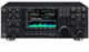
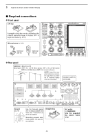
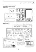
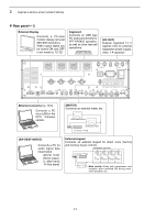
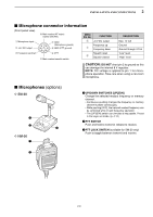
2 INSTALLATION AND CONNECTIONS D Rear panel- 2 External Display Connects a PC-style monitor display (at least 800×600 resolution). Video output signal can be turned ON and OFF in set mode (p. 12-12) Keyboard Connects an USB type PC keyboard directly for RTTY/PSK31 operation, as well as other text edit operations. [DC OUT] Outputs regulated 14 V (approx.) DC for external equipment power supply. (max. 1 A capacity) EXT-DISPLAY OUT IN RX ANT B X-VERTER OUT IN RX ANT A I ANT 1 ANT 2 ANT 3 ANT 4 AC GND KEY BOARD RS-232C REMOTE S/P DID OUT IN REF I/O 10MHz -10dBm DC OUT 15V EXT MAX1A METER KEYPAD KEY RELAY ALC ALC ADJ B ACC 2 ACC 1 A ACC 2 ACC 1 EXT-SP SUB MAIN Ethernet connector (p. 16-6) Connects a PC via a LAN for the CPU firmware update. [METER] Connects an external meter, etc. MAIN band meter SUB band meter 3.5 (d) mm; 1⁄8≤ plug [S/P DEAF IN/OUT] Connects a PC for audio signal data input/output. 48 kHz, 16-bit Stereo output (L=Main band; R=Sub band) External keypad Connects an external keypad for direct voice memory and memory keyer controls. EXTERNAL KEYPAD 3.5 (d) mm; 1⁄8≤ plug 1.5 kΩ 1.5 kΩ 2.2 kΩ 4.7 kΩ ±5% ±5% ±5% ±5% S1 S2 S3 S4 (T1/M1) (T2/M2) (T3/M3) (T4/M4) Mute switch: Mutes both transmission and reception when switched ON during transceive operation, etc. 2-6
-
 1
1 -
2
-
3
-
4
-
5
-
6
-
7
-
8
-
9
-
10
-
11
-
12
-
13
-
14
-
15
-
16
-
17
-
18
-
19
-
20
-
21
-
22
-
23
-
24
-
25
-
 26
26 -
 27
27 -
 28
28 -
 29
29 -
 30
30 -
 31
31 -
 32
32 -
 33
33 -
 34
34 -
 35
35 -
 36
36 -
37
-
38
-
39
-
40
-
41
-
42
-
43
-
44
-
45
-
46
-
47
-
48
-
49
-
50
-
51
-
52
-
53
-
54
-
55
-
56
-
57
-
58
-
59
-
60
-
61
-
62
-
63
-
64
-
65
-
66
-
67
-
68
-
69
-
70
-
71
-
72
-
73
-
74
-
75
-
76
-
77
-
78
-
79
-
80
-
81
-
82
-
83
-
84
-
85
-
86
-
87
-
88
-
89
-
90
-
91
-
92
-
93
-
94
-
95
-
96
-
97
-
98
-
99
-
100
-
101
-
102
-
103
-
104
-
105
-
106
-
107
-
108
-
109
-
110
-
111
-
112
-
113
-
114
-
115
-
116
-
117
-
118
-
119
-
120
-
121
-
122
-
123
-
124
-
125
-
126
-
127
-
128
-
129
-
130
-
131
-
132
-
133
-
134
-
135
-
136
-
137
-
138
-
139
-
140
-
141
-
142
-
143
-
144
-
145
-
146
-
147
-
148
-
149
-
150
-
151
-
152
-
153
-
154
-
155
-
156
-
157
-
158
-
159
-
160
-
161
-
162
-
163
-
164
-
165
-
166
-
167
-
168
-
169
-
170
-
171
-
172
-
173
-
174
-
175
-
176
-
177
-
178
-
179
-
180
-
181
-
182
-
183
-
184
-
185
-
186
-
187
-
188
-
189
-
190
-
191
-
192
-
193
-
194
-
195
-
196
-
197
-
198
-
199
-
200
-
201
-
202
-
203
-
204
-
205
-
206
 |
 |
