Icom IC-7800 Instruction Manual - Page 22
Rear panel - problems
 |
View all Icom IC-7800 manuals
Add to My Manuals
Save this manual to your list of manuals |
Page 22 highlights
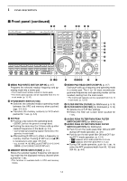
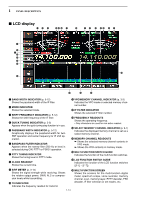
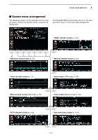
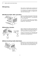
1 PANEL DESCRIPTION I Rear panel q w e r t y u i o !0 !1 E X T- DISPL AY OUT IN RX ANT B X-VERTER OUT IN RX ANT A I ANT 1 ANT 2 ANT 3 ANT 4 AC GND KEY BOARD RS-232C REMOTE S/P DIF OUT IN REF I/O 10MHz -10dBm DC OUT 15V EXT MAX1A METER KEYPAD KEY RELAY ALC ALC ADJ B ACC 2 ACC 1 A ACC 2 ACC 1 E X T- SP SUB MAIN !2 !3 #3 #4 #2 #1 #0 @9 @8 @7 @6 @5 @4 @3 @2 @1 @0 !9 !8 !7 !6 !5 !4 q ANTENNA CONNECTOR 1 [ANT 1] (p. 2-4) w ANTENNA CONNECTOR 2 [ANT 2] (p. 2-4) e ANTENNA CONNECTOR 3 [ANT 3] (p. 2-4) r ANTENNA CONNECTOR 4 [ANT 4] (p. 2-4) Accept a 50 Ω antenna with a PL-259 plug connector. t GROUND TERMINAL [GND] (p. 2-3) Connect this terminal to a ground to prevent electrical shocks, TVI, BCI and other problems. y CIRCUIT BREAKER Cuts off the AC input when over-current occurs. u RECEIVE ANTENNA B OUT [RX ANT B- OUT] i RECEIVE ANTENNA B IN [RX ANT B- IN] Located between the transmit/receive switching circuit and receiver's RF stage in SUB band (MAIN band during split operation). Connects an external unit, such as preamplifier or RF filter, using BNC connectors, if desired. When no external unit is connected, [RX ANT B- OUT] and [RX ANT B- IN] must be shorted with the supplied coaxial cable. (p. 2-2) Receiver [RX ANT A/B] IN OUT Transmitter Transmit/Receive switching circuit o TRANSVERTER CONNECTOR [X-VERTER] (p. 2-5) External transverter input/output connector. Activated by voltage applied to [ACC 2] pin 6, or when the transverter function is in use. (pgs. 2-10, 4-6) !0 RECEIVE ANTENNA A OUT [RX ANT A- OUT] !1 RECEIVE ANTENNA A IN [RX ANT A- IN] Located between the transmit/receive switching circuit and receiver's RF stage in MAIN band (SUB band during split operation). Connects an external unit, such as preamplifier or RF filter, using BNC connectors, if desired. When no external unit is connected, [RX ANT A- OUT] and [RX ANT A- IN] must be shorted with the supplied coaxial cable. (p. 2-2) !2 MAIN POWER SWITCH [I/O] (p. 3-2) Turns the internal power supply ON and OFF. !3 AC POWER SOCKET [AC] (p. 2-4) Connects the supplied AC power cable to an AC line-voltage receptacle. !4 EXTERNAL SPEAKER JACK MAIN [EXT-SP MAIN] (p. 2-5) !5 EXTERNAL SPEAKER JACK SUB [EXT-SP SUB] (p. 2-5) Connects an external speaker (4-8 Ω), if desired. 1-12
-
 1
1 -
2
-
3
-
4
-
5
-
6
-
7
-
8
-
9
-
10
-
11
-
12
-
13
-
14
-
15
-
16
-
 17
17 -
 18
18 -
 19
19 -
 20
20 -
 21
21 -
 22
22 -
 23
23 -
 24
24 -
 25
25 -
 26
26 -
 27
27 -
28
-
29
-
30
-
31
-
32
-
33
-
34
-
35
-
36
-
37
-
38
-
39
-
40
-
41
-
42
-
43
-
44
-
45
-
46
-
47
-
48
-
49
-
50
-
51
-
52
-
53
-
54
-
55
-
56
-
57
-
58
-
59
-
60
-
61
-
62
-
63
-
64
-
65
-
66
-
67
-
68
-
69
-
70
-
71
-
72
-
73
-
74
-
75
-
76
-
77
-
78
-
79
-
80
-
81
-
82
-
83
-
84
-
85
-
86
-
87
-
88
-
89
-
90
-
91
-
92
-
93
-
94
-
95
-
96
-
97
-
98
-
99
-
100
-
101
-
102
-
103
-
104
-
105
-
106
-
107
-
108
-
109
-
110
-
111
-
112
-
113
-
114
-
115
-
116
-
117
-
118
-
119
-
120
-
121
-
122
-
123
-
124
-
125
-
126
-
127
-
128
-
129
-
130
-
131
-
132
-
133
-
134
-
135
-
136
-
137
-
138
-
139
-
140
-
141
-
142
-
143
-
144
-
145
-
146
-
147
-
148
-
149
-
150
-
151
-
152
-
153
-
154
-
155
-
156
-
157
-
158
-
159
-
160
-
161
-
162
-
163
-
164
-
165
-
166
-
167
-
168
-
169
-
170
-
171
-
172
-
173
-
174
-
175
-
176
-
177
-
178
-
179
-
180
-
181
-
182
-
183
-
184
-
185
-
186
-
187
-
188
-
189
-
190
-
191
-
192
-
193
-
194
-
195
-
196
-
197
-
198
-
199
-
200
-
201
-
202
-
203
-
204
-
205
-
206
 |
 |
