Intel X38ML Product Specification - Page 108
Timestamp Clock Event
 |
UPC - 735858197397
View all Intel X38ML manuals
Add to My Manuals
Save this manual to your list of manuals |
Page 108 highlights
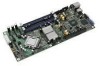
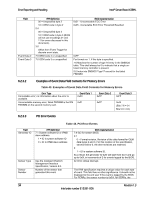
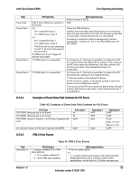
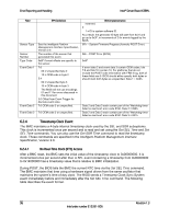
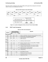
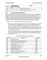
Error Reporting and Handling Intel® Server Board X38ML Field Sensor Type Sensor Number Type Code Event Data 1 Event Data 2 Event Data 3 IPMI Definition See the Intelligent Platform Management Interface Specification, Version 2.0. The number of the sensor that generated this event. 0x6F if event offsets are specific to the sensor. 7:6 00 = Unspecified byte 2 10 = OEM code in byte 2 5:4 00 = Unspecified byte 3 10 = OEM code in byte 3. The BIOS will not use encodings 01 and 11 for errors discussed in this document. 3:0 Offset from Event Trigger for discrete event state. 7:0 OEM code 2 or unspecified. 7:0 OEM code 3 or unspecified. reserved. BIOS Implementation 0 1 = ID is system software ID. As a result, the generator ID byte will start from 0x31 and go up to 0x3F, in increments of 2 for events logged by the BIOS. 0Fh - System Firmware Progress (formerly POST Error) 06h - POST Error (BIOS) 0x6F If event data 2 and event data 3 contain OEM codes, bits 7:6 and bits 5:4 contain 10. For platforms that do not include the POST code information with FRB-2 log, both of these fields are 0. BIOS should either specify both bytes or should mark both bytes as unspecified. Data 1 = 0A0h. Data 2 and Data 3 each contain part of the 'Watchdog timer failed on last boot' error code 8190. Data 2 = 090h. Data 2 and Data 3 each contain part of the 'Watchdog timer failed on last boot' error code 8190. Data 3 = 081h. 6.2.4 Timestamp Clock Event The BMC maintains a 4-byte internal timestamp clock used by the SEL and SDR subsystems. This clock is incremented once per second and is read and set using the Get SEL Time and Set SEL Time commands. You can also use the Get SDR Time command to read the timestamp clock. These commands are specified in the Intelligent Platform Management Interface Specification, Version 2.0. 6.2.4.1 No Real-Time Clock (RTC) Access After a BMC reset, the BMC sets the initial value of the timestamp clock to 0x00000000. It is incremented once per second after that. A SEL event containing a timestamp from 0x00000000 to 0x14000000 has a timestamp value that is relative to BMC initialization. During POST, the BIOS tells the BMC the current RTC time via the Set SEL Time command. The BMC maintains that time using a hardware signal driven from the same oscillator that maintains the system's time-of-day clock. The BIOS sends a Timestamp Clock Sync System event immediately before and immediately after the Set SEL Time command. The following table describes the event format. 96 Revision 1.3 Intel order number E15331-006
-
 1
1 -
2
-
3
-
4
-
5
-
6
-
7
-
8
-
9
-
10
-
11
-
12
-
13
-
14
-
15
-
16
-
17
-
18
-
19
-
20
-
21
-
22
-
23
-
24
-
25
-
26
-
27
-
28
-
29
-
30
-
31
-
32
-
33
-
34
-
35
-
36
-
37
-
38
-
39
-
40
-
41
-
42
-
43
-
44
-
45
-
46
-
47
-
48
-
49
-
50
-
51
-
52
-
53
-
54
-
55
-
56
-
57
-
58
-
59
-
60
-
61
-
62
-
63
-
64
-
65
-
66
-
67
-
68
-
69
-
70
-
71
-
72
-
73
-
74
-
75
-
76
-
77
-
78
-
79
-
80
-
81
-
82
-
83
-
84
-
85
-
86
-
87
-
88
-
89
-
90
-
91
-
92
-
93
-
94
-
95
-
96
-
97
-
98
-
99
-
100
-
101
-
102
-
 103
103 -
 104
104 -
 105
105 -
 106
106 -
 107
107 -
 108
108 -
 109
109 -
 110
110 -
 111
111 -
 112
112 -
 113
113 -
114
-
115
-
116
-
117
-
118
-
119
-
120
-
121
-
122
-
123
-
124
-
125
-
126
-
127
-
128
-
129
-
130
-
131
-
132
 |
 |