Intel X38ML Product Specification - Page 109
Error Messages and Error Codes
 |
UPC - 735858197397
View all Intel X38ML manuals
Add to My Manuals
Save this manual to your list of manuals |
Page 109 highlights
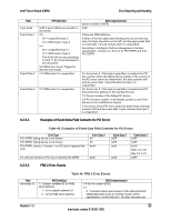
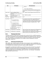
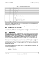
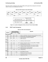
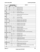
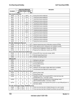
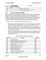
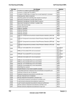
Intel® Server Board X38ML Error Reporting and Handling Table 47. Timestamp Clock Sync Format Offset 1 2 3 4 5 6 7 8 Value 03h 04h 12h 83h 6Fh 05h FFh Generator ID Description Event Message Revision System Event Boot Event Sensor Event Type Boot Event [7] - First/second 0b = Event is first of the pair 1b = Event is second of the pair [6:4] Reserved [3:0] Timestamp clock sync 0b = SEL Timestamp clock updated 1b = SDR Timestamp clock updated No data When the user changes the real-time clock (RTC) during operation, the SMS is responsible for keeping the BMC and system time in sync. Note: The BMC could lose the current timestamp during a BMC cold reset or a firmware update. 6.3 Error Messages and Error Codes The system BIOS displays POST error codes and error messages on the video screen. Before video initialization, POST error codes are logged in the event log. 6.3.1 Diagnostic LEDs During the system boot process, the BIOS executes several platform configuration processes, each of which is assigned a specific hex POST code number. As each configuration routine is started, the BIOS displays the POST code on the POST code diagnostic LEDs found on the back edge of the server board. To assist in troubleshooting a system hang during the POST process, you can use the diagnostic LEDs to identify the last POST process to be executed. Each POST code is represented by a combination of colors from the four LEDs. The LEDs are capable of displaying three colors: green, red, and amber. The POST codes are divided into an upper nibble and a lower nibble. Each bit in the upper nibble is represented by a red LED and each bit in the lower nibble is represented by a green LED. If both bits are set in the upper and lower nibbles then both red and green LEDs are lit, resulting in an amber color. If both bits are clear, then the LED is off. In the following example, the BIOS sends a value of ACh to the diagnostic LED decoder. The LEDs are decoded as follows: ƒ Red bits = 1010b = Ah ƒ Green bits = 1100b = Ch Revision 1.3 97 Intel order number E15331-006
-
 1
1 -
2
-
3
-
4
-
5
-
6
-
7
-
8
-
9
-
10
-
11
-
12
-
13
-
14
-
15
-
16
-
17
-
18
-
19
-
20
-
21
-
22
-
23
-
24
-
25
-
26
-
27
-
28
-
29
-
30
-
31
-
32
-
33
-
34
-
35
-
36
-
37
-
38
-
39
-
40
-
41
-
42
-
43
-
44
-
45
-
46
-
47
-
48
-
49
-
50
-
51
-
52
-
53
-
54
-
55
-
56
-
57
-
58
-
59
-
60
-
61
-
62
-
63
-
64
-
65
-
66
-
67
-
68
-
69
-
70
-
71
-
72
-
73
-
74
-
75
-
76
-
77
-
78
-
79
-
80
-
81
-
82
-
83
-
84
-
85
-
86
-
87
-
88
-
89
-
90
-
91
-
92
-
93
-
94
-
95
-
96
-
97
-
98
-
99
-
100
-
101
-
102
-
103
-
 104
104 -
 105
105 -
 106
106 -
 107
107 -
 108
108 -
 109
109 -
 110
110 -
 111
111 -
 112
112 -
 113
113 -
 114
114 -
115
-
116
-
117
-
118
-
119
-
120
-
121
-
122
-
123
-
124
-
125
-
126
-
127
-
128
-
129
-
130
-
131
-
132
 |
 |
