Intel X38ML Product Specification - Page 116
Connectors and Jumper Blocks - specs
 |
UPC - 735858197397
View all Intel X38ML manuals
Add to My Manuals
Save this manual to your list of manuals |
Page 116 highlights
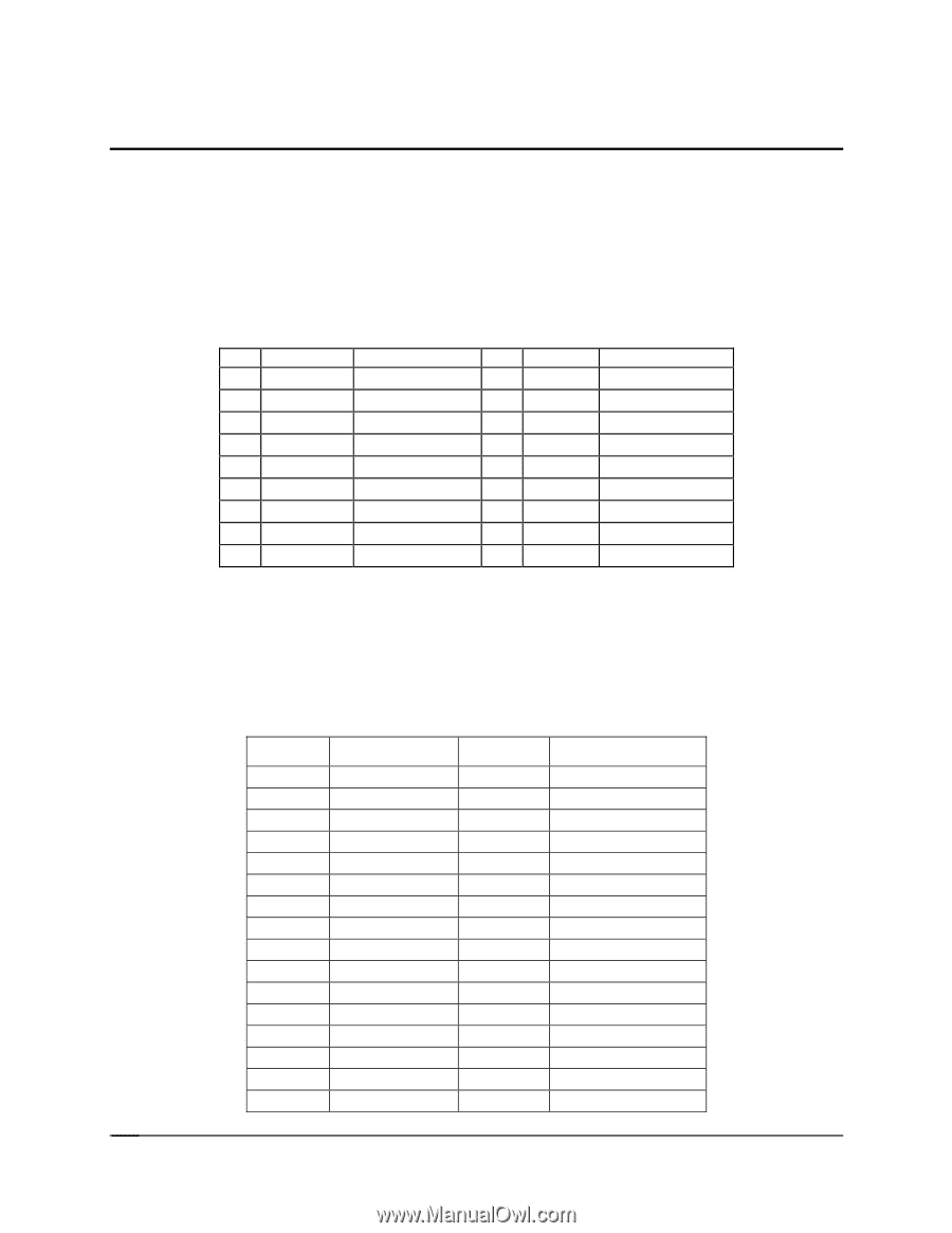
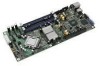
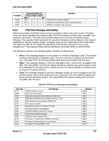
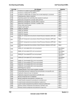
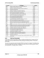
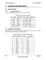
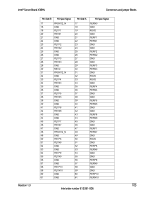
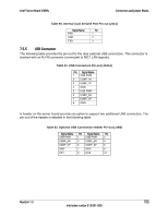
Connectors and Jumper Blocks Intel® Server Board X38ML 7. Connectors and Jumper Blocks 7.1 Power Connectors 7.1.1 Main Power Connector The following table defines the pin-out of the main power connector: Table 51. Power Connector Pin-out (J4K1) Pin Signal 1 +3.3V 18 AWG Color Orange 2 GND Black 3 GND Black 4 +5V Red 5 +5VSB Purple 6 GND Black 7 GND Black 8 P12V_VRD Yellow 9 P12V_VRD Yellow Pin Signal 10 +3.3V 18 AWG Color Orange 11 -12V Blue 12 GND Black 13 PS_ON# Green 14 +5V Red 15 PWROK Gray 16 GND Black 17 GND Black 18 +12V Yellow/Blue Stripe 7.2 PCI Express* x16 Connector One PCI Express* x16 connector is provided to support PCI Express* riser cards. The following table defines the pin-out of the PCI Express x16 connector: Table 52. PCI Express* x16 Connector Pin-out (J7B1) Pin-Side B PCI Spec Signal 1 12V 2 12V 3 RSVD 4 GND 5 SMCLK 6 SMDAT 7 GND 8 3_3V 9 JTAG1 10 3_3VAUX 11 WAKE_N 12 RSVD 13 GND 14 PETP0 15 PETN0 16 GND Pin-Side A 1 2 3 4 5 6 7 8 9 10 11 12 13 14 15 16 PCI Spec Signal PRSNT1_N 12V 12V GND JTAG2 JTAG3 JTAG4 JTAG5 3_3V 3_3V PERST_N GND REFCLK+ REFCLKGND PERP0 104 Revision 1.3 Intel order number E15331-006
-
 1
1 -
2
-
3
-
4
-
5
-
6
-
7
-
8
-
9
-
10
-
11
-
12
-
13
-
14
-
15
-
16
-
17
-
18
-
19
-
20
-
21
-
22
-
23
-
24
-
25
-
26
-
27
-
28
-
29
-
30
-
31
-
32
-
33
-
34
-
35
-
36
-
37
-
38
-
39
-
40
-
41
-
42
-
43
-
44
-
45
-
46
-
47
-
48
-
49
-
50
-
51
-
52
-
53
-
54
-
55
-
56
-
57
-
58
-
59
-
60
-
61
-
62
-
63
-
64
-
65
-
66
-
67
-
68
-
69
-
70
-
71
-
72
-
73
-
74
-
75
-
76
-
77
-
78
-
79
-
80
-
81
-
82
-
83
-
84
-
85
-
86
-
87
-
88
-
89
-
90
-
91
-
92
-
93
-
94
-
95
-
96
-
97
-
98
-
99
-
100
-
101
-
102
-
103
-
104
-
105
-
106
-
107
-
108
-
109
-
110
-
 111
111 -
 112
112 -
 113
113 -
 114
114 -
 115
115 -
 116
116 -
 117
117 -
 118
118 -
 119
119 -
 120
120 -
 121
121 -
122
-
123
-
124
-
125
-
126
-
127
-
128
-
129
-
130
-
131
-
132
 |
 |