Intel X38ML Product Specification - Page 118
Front Panel Connector
 |
UPC - 735858197397
View all Intel X38ML manuals
Add to My Manuals
Save this manual to your list of manuals |
Page 118 highlights
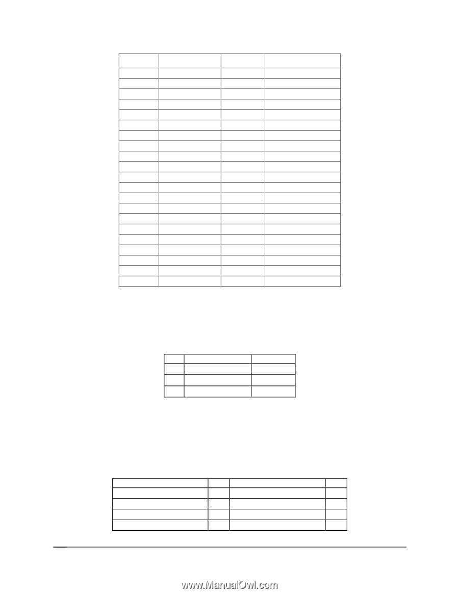
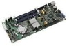
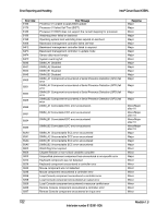
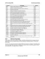
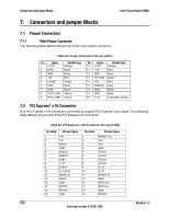
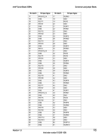
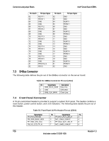
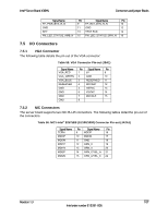
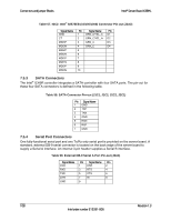
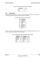
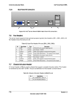
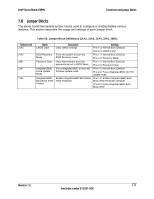
Connectors and Jumper Blocks Intel® Server Board X38ML Pin-Side B PCI Spec Signal 62 PETP11 63 PETN11 64 GND 65 GND 66 PETP12 67 PETN12 68 GND 69 GND 70 PETP13 71 PETN13 72 GND 73 GND 74 PETP14 75 PETN14 76 GND 77 GND 78 PETP15 79 PETN15 80 GND 81 PRSNT2_N 82 RSVD Pin-Side A 62 63 64 65 66 67 68 69 70 71 72 73 74 75 76 77 78 79 80 81 82 PCI Spec Signal GND GND PERP11 PERN11 GND GND PERP12 PERN12 GND GND PERP13 PERN13 GND GND PERP14 PERN14 GND GND PERP15 PERN15 GND 7.3 SMBus Connector The following table defines the pin-out of the SMBus connector on the server board: Table 53. SMBus Connector Pin-out (J3C1) Pin Signal Name Description 1 SMB_DATA_MAIN Data Line 2 GND GROUND 3 SMB_CLK_MAIN Clock Line 7.4 Front Panel Connector A 16-pin customized header is provided to support a system front panel. The header contains a reset button, power control button, and LED indicators. The following table details the pin-out of this header: Table 54. Front Panel 16-Pin Header Pin-out (J5K4) Signal Name FP_P3V3_ANODE FM_GRN_BLNK_HDR FP_HDD_LED_VCC FM_HD_LED_FP_N Pin Signal Name Pin 1 FP_NIC1_ACT_LED_R 2 3 NIC_LINKA_LINKUP 4 5 FP_NIC2_ACT_LED_R 6 7 NIC_LINKB_LINKUP 8 106 Revision 1.3 Intel order number E15331-006
-
 1
1 -
2
-
3
-
4
-
5
-
6
-
7
-
8
-
9
-
10
-
11
-
12
-
13
-
14
-
15
-
16
-
17
-
18
-
19
-
20
-
21
-
22
-
23
-
24
-
25
-
26
-
27
-
28
-
29
-
30
-
31
-
32
-
33
-
34
-
35
-
36
-
37
-
38
-
39
-
40
-
41
-
42
-
43
-
44
-
45
-
46
-
47
-
48
-
49
-
50
-
51
-
52
-
53
-
54
-
55
-
56
-
57
-
58
-
59
-
60
-
61
-
62
-
63
-
64
-
65
-
66
-
67
-
68
-
69
-
70
-
71
-
72
-
73
-
74
-
75
-
76
-
77
-
78
-
79
-
80
-
81
-
82
-
83
-
84
-
85
-
86
-
87
-
88
-
89
-
90
-
91
-
92
-
93
-
94
-
95
-
96
-
97
-
98
-
99
-
100
-
101
-
102
-
103
-
104
-
105
-
106
-
107
-
108
-
109
-
110
-
111
-
112
-
 113
113 -
 114
114 -
 115
115 -
 116
116 -
 117
117 -
 118
118 -
 119
119 -
 120
120 -
 121
121 -
 122
122 -
 123
123 -
124
-
125
-
126
-
127
-
128
-
129
-
130
-
131
-
132
 |
 |