Intel X38ML Product Specification - Page 75
Front Panel/Chassis Inputs, Front Panel Lock-out Operation
 |
UPC - 735858197397
View all Intel X38ML manuals
Add to My Manuals
Save this manual to your list of manuals |
Page 75 highlights
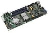
Intel® Server Board X38ML Platform Management Color State Amber Solid on Off N/A System Status Fatal Not ready Description Fatal alarm - system has failed or shutdown. Condition detected by BMC. ƒ CPU IERR signal asserted ƒ CPU THERMTRIP ƒ No power good - power fault Power off Note: Support for upper non-critical state is not provided in default SDR configuration. If a user enables this threshold in the SDR, then the system status LED behaves as described. 5.7.3 Front Panel/Chassis Inputs The BMC monitors the front panel buttons and other chassis signals. The front panel input buttons are momentary contact switches that are de-bounced by the BMC's integrated hardware. The de-bounce time is 8 ms; the signal must be in a constant low state for 8 ms before it is treated as asserted. BMC de-bouncing does not affect the operation of the power or reset button, since the power and reset buttons are connected to the chipset. The de-bouncing is only for BMC monitoring. 5.7.3.1 Chassis Intrusion Chassis intrusion detection is supported. The BMC monitors the state of the Chassis Intrusion signal and makes the status of the signal available via the Get Chassis Status command and the Physical Security sensor state. A chassis intrusion state change causes the BMC to generate a Physical Security sensor event message with a General Chassis Intrusion offset (00h). The BMC boosts all fans when the chassis intrusion signal is active. Fans return to their previous level when the chassis intrusion signal is no longer active. This provides sufficient cooling during system servicing. The BMC monitors the chassis intrusion cable. If the cable is missing, the BMC logs a SEL event and sets the chassis intrusion status to the init-in-progress state. The BMC detects chassis intrusion and logs a SEL event when the system is in an on, sleep, or standby state. Chassis intrusion is not detected when the system is in an AC power-off state. 5.7.3.2 Power Button See Section 5.2.5.1. 5.7.3.3 Reset Button An assertion of the Front Panel Reset signal to the BMC causes the system to start the reset and reboot process, as long as the BMC has not locked-out this input. This assertion is immediate and without the cooperation of software or the operating system. See Section 5.4.3. 5.7.4 Front Panel Lock-out Operation You can lock the front panel using the Set Front Panel Enables command. You can check the front panel lock-out status using the Get chassis Status command. Revision 1.3 63 Intel order number E15331-006
-
 1
1 -
2
-
3
-
4
-
5
-
6
-
7
-
8
-
9
-
10
-
11
-
12
-
13
-
14
-
15
-
16
-
17
-
18
-
19
-
20
-
21
-
22
-
23
-
24
-
25
-
26
-
27
-
28
-
29
-
30
-
31
-
32
-
33
-
34
-
35
-
36
-
37
-
38
-
39
-
40
-
41
-
42
-
43
-
44
-
45
-
46
-
47
-
48
-
49
-
50
-
51
-
52
-
53
-
54
-
55
-
56
-
57
-
58
-
59
-
60
-
61
-
62
-
63
-
64
-
65
-
66
-
67
-
68
-
69
-
 70
70 -
 71
71 -
 72
72 -
 73
73 -
 74
74 -
 75
75 -
 76
76 -
 77
77 -
 78
78 -
 79
79 -
 80
80 -
81
-
82
-
83
-
84
-
85
-
86
-
87
-
88
-
89
-
90
-
91
-
92
-
93
-
94
-
95
-
96
-
97
-
98
-
99
-
100
-
101
-
102
-
103
-
104
-
105
-
106
-
107
-
108
-
109
-
110
-
111
-
112
-
113
-
114
-
115
-
116
-
117
-
118
-
119
-
120
-
121
-
122
-
123
-
124
-
125
-
126
-
127
-
128
-
129
-
130
-
131
-
132
 |
 |