Intel X38ML Product Specification - Page 120
SATA Connectors, Serial Port Connectors
 |
UPC - 735858197397
View all Intel X38ML manuals
Add to My Manuals
Save this manual to your list of manuals |
Page 120 highlights
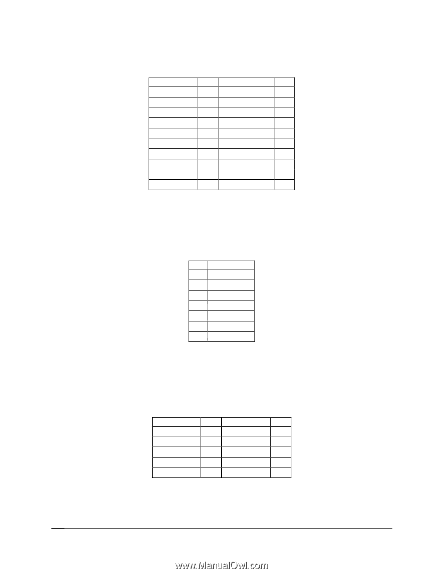
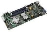
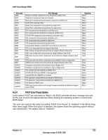
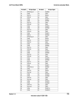
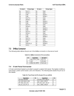
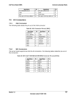
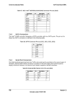
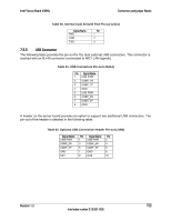
Connectors and Jumper Blocks Intel® Server Board X38ML Table 57. NIC2- Intel® 82575EB (10/100/1000) Connector Pin-out (J3A2) Signal Name Pin Signal Name Pin GND 1 GRN_A/YEL_C D1 CT 2 GRN_C/YEL_A D2 MDI3P 3 GRN_A D3 MDI3N 4 GRN_C D4 MDI2P 5 MDI2N 6 MDI1P 7 MDI1N 8 MDI0P 9 MDI0N 10 7.5.3 SATA Connectors The Intel® ICH9R controller integrates a SATA controller with four SATA ports. The pin-out for these four SATA connectors is defined in the following table. Table 58. SATA Connector Pin-out (J1C1, J1C2, J2C2, J2C1) Pin Signal Name 1 GND 2 TXP 3 TXN 4 GND 5 RXN 6 RXP 7 GND 7.5.4 Serial Port Connectors One fully-functional serial port and one Tx/Rx only serial port is provided on the server board. A standard, external DB-9 serial connector is located on the back edge of the server board to supply a Serial A interface. An internal 3-pin header supplies a Serial B interface. Table 59. External DB-9 Serial A Port Pin-out (J5A1) Signal Name Pin Signal Name Pin DCD 1 DSR 2 RXD 3 RTS 4 TXD 5 CTS 6 DTR 7 RI 8 GND 9 108 Revision 1.3 Intel order number E15331-006
-
 1
1 -
2
-
3
-
4
-
5
-
6
-
7
-
8
-
9
-
10
-
11
-
12
-
13
-
14
-
15
-
16
-
17
-
18
-
19
-
20
-
21
-
22
-
23
-
24
-
25
-
26
-
27
-
28
-
29
-
30
-
31
-
32
-
33
-
34
-
35
-
36
-
37
-
38
-
39
-
40
-
41
-
42
-
43
-
44
-
45
-
46
-
47
-
48
-
49
-
50
-
51
-
52
-
53
-
54
-
55
-
56
-
57
-
58
-
59
-
60
-
61
-
62
-
63
-
64
-
65
-
66
-
67
-
68
-
69
-
70
-
71
-
72
-
73
-
74
-
75
-
76
-
77
-
78
-
79
-
80
-
81
-
82
-
83
-
84
-
85
-
86
-
87
-
88
-
89
-
90
-
91
-
92
-
93
-
94
-
95
-
96
-
97
-
98
-
99
-
100
-
101
-
102
-
103
-
104
-
105
-
106
-
107
-
108
-
109
-
110
-
111
-
112
-
113
-
114
-
 115
115 -
 116
116 -
 117
117 -
 118
118 -
 119
119 -
 120
120 -
 121
121 -
 122
122 -
 123
123 -
 124
124 -
 125
125 -
126
-
127
-
128
-
129
-
130
-
131
-
132
 |
 |