Intel X38ML Product Specification - Page 71
System Reset Control
 |
UPC - 735858197397
View all Intel X38ML manuals
Add to My Manuals
Save this manual to your list of manuals |
Page 71 highlights
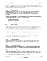
Intel® Server Board X38ML Platform Management 5.3.2 ACPI State Synchronization The BIOS keeps the BMC synchronized with the system ACPI state. The BIOS provides the ACPI state when the server transitions between the power and the sleep states. It uses the SMM interface to provide the ACPI state. 5.4 System Reset Control 5.4.1 Reset Signal Output The BMC simulates a press of the front panel reset button to perform a system reset. The ICH performs the rest of the system reset process. The BMC cannot hold the system in reset, and once started, the process is asynchronous with respect to BMC operation. The BMC provides system status indication through the front panel LEDs. See Section 5.7.2. The reset portion of the power-on process is performed by the ICH. 5.4.2 Reset Control Sources All system resets result in the BMC running a sensor initialization agent service. See Section 5.12.2. Table 29. System Reset Sources and Actions Reset Source Main system power comes up Reset button or in-target probe (ITP) reset Soft reset/warm boot (DOS Ctrl-Alt-Del) Hard reset Command to reset the system Watchdog timer configured for reset PEF action System Reset? Yes Yes Yes Yes Yes Yes Optional 5.4.3 Front Panel System Reset The reset button is a momentary contact button on the front panel. The signal is routed through the front panel connector to the BMC, which monitors and de-bounces it. The signal must be stable for at least 50 ms before a state change is recognized. If the reset button is locked by the BMC, then the button does not reset the system. Instead, a platform security violation attempt event message is generated if the reset button is pressed. 5.4.4 Soft Reset and Hard Reset The BMC monitors an ICH signal called BIOS_POST_CMPLT_N, which de-asserts at the beginning of POST and asserts at the end of POST. The signal de-assertion indicates a system reset has occurred. The BMC monitors this signal to detect both hard resets and soft resets. The BIOS converts all INITs into hard resets. Therefore, INITs also result in the BMC sensing a system reset. The BMC detects these resets but does not participate in the reset mechanism. Revision 1.3 59 Intel order number E15331-006
-
 1
1 -
2
-
3
-
4
-
5
-
6
-
7
-
8
-
9
-
10
-
11
-
12
-
13
-
14
-
15
-
16
-
17
-
18
-
19
-
20
-
21
-
22
-
23
-
24
-
25
-
26
-
27
-
28
-
29
-
30
-
31
-
32
-
33
-
34
-
35
-
36
-
37
-
38
-
39
-
40
-
41
-
42
-
43
-
44
-
45
-
46
-
47
-
48
-
49
-
50
-
51
-
52
-
53
-
54
-
55
-
56
-
57
-
58
-
59
-
60
-
61
-
62
-
63
-
64
-
65
-
 66
66 -
 67
67 -
 68
68 -
 69
69 -
 70
70 -
 71
71 -
 72
72 -
 73
73 -
 74
74 -
 75
75 -
 76
76 -
77
-
78
-
79
-
80
-
81
-
82
-
83
-
84
-
85
-
86
-
87
-
88
-
89
-
90
-
91
-
92
-
93
-
94
-
95
-
96
-
97
-
98
-
99
-
100
-
101
-
102
-
103
-
104
-
105
-
106
-
107
-
108
-
109
-
110
-
111
-
112
-
113
-
114
-
115
-
116
-
117
-
118
-
119
-
120
-
121
-
122
-
123
-
124
-
125
-
126
-
127
-
128
-
129
-
130
-
131
-
132
 |
 |