Intel X38ML Product Specification - Page 74
Integrated Front Panel User Interface
 |
UPC - 735858197397
View all Intel X38ML manuals
Add to My Manuals
Save this manual to your list of manuals |
Page 74 highlights
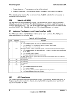
Platform Management Intel® Server Board X38ML The BMC does not guarantee any specific rate at which the FIFO's contents are displayed to the LEDs. 5.7 Integrated Front Panel User Interface The front panel has the following indicators: ƒ Power LED ƒ System status/fault LED The front panel provides the following buttons: ƒ Reset button ƒ Power button 5.7.1 Power LED The BMC does not control the Power Status LED. See the system BIOS EPS for details on Power Status LED states. 5.7.2 System Status LED Note: The system status LED state shows the state for the current, most severe fault. For example, if there was a critical fault due to one source and a non-critical fault due to another source, the system status LED state would be solid on (the state for the critical fault). The system status/fault LED is a bicolor LED. Green (status) is used to show a normal operation state or a degraded operation. Amber (fault) shows the platform hardware state and overrides the green status. The system status LED is controlled by the BMC. Early in the startup boot process, the BIOS checks the chipset for any memory errors. The BMC-detected states are included in the LED states. For fault states monitored by BMC sensors, the contribution to the LED state follows the associated sensor state, with priority given to the most critical asserted state. When the server is powered down (transitions to the DC-off state or S5), the BMC is still on standby power and retains the sensor and front panel status LED state established before the power-down event. The LED state information in Table 31 is dependent on the underlying sensor support. Color Green Green Amber State Solid on ~1 Hz blink ~1 Hz blink Table 31. System Status LED Indicator States System Status Ok Degraded Non-fatal System ready Description Condition detected by BMC. ƒ CPU disabled ƒ Non-critical threshold crossed - temperature, voltage Non-fatal alarm. The system is likely to fail. Condition detected by the BMC. ƒ Critical threshold crossed - temperature 62 Revision 1.3 Intel order number E15331-006
-
 1
1 -
2
-
3
-
4
-
5
-
6
-
7
-
8
-
9
-
10
-
11
-
12
-
13
-
14
-
15
-
16
-
17
-
18
-
19
-
20
-
21
-
22
-
23
-
24
-
25
-
26
-
27
-
28
-
29
-
30
-
31
-
32
-
33
-
34
-
35
-
36
-
37
-
38
-
39
-
40
-
41
-
42
-
43
-
44
-
45
-
46
-
47
-
48
-
49
-
50
-
51
-
52
-
53
-
54
-
55
-
56
-
57
-
58
-
59
-
60
-
61
-
62
-
63
-
64
-
65
-
66
-
67
-
68
-
 69
69 -
 70
70 -
 71
71 -
 72
72 -
 73
73 -
 74
74 -
 75
75 -
 76
76 -
 77
77 -
 78
78 -
 79
79 -
80
-
81
-
82
-
83
-
84
-
85
-
86
-
87
-
88
-
89
-
90
-
91
-
92
-
93
-
94
-
95
-
96
-
97
-
98
-
99
-
100
-
101
-
102
-
103
-
104
-
105
-
106
-
107
-
108
-
109
-
110
-
111
-
112
-
113
-
114
-
115
-
116
-
117
-
118
-
119
-
120
-
121
-
122
-
123
-
124
-
125
-
126
-
127
-
128
-
129
-
130
-
131
-
132
 |
 |