Intel X38ML Product Specification - Page 30
Super I/O Chip
 |
UPC - 735858197397
View all Intel X38ML manuals
Add to My Manuals
Save this manual to your list of manuals |
Page 30 highlights
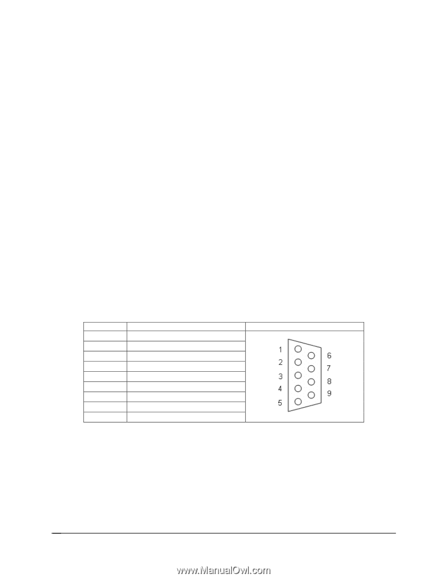
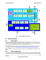
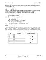
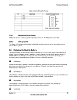
Functional Architecture Intel® Server Board X38ML baseboard. One 10-pin internal on-board header is provided which is capable of supporting two additional USB 2.0 ports. 3.5.6 Super I/O Chip The Super I/O chip integrated into the Integrated BMC provides legacy I/O support. The Super I/O chip contains the necessary circuitry to support two serial ports and hardware control/monitor functions. The server board implements the following features: ƒ Two fully functional serial ports, compatible with the 16C550 ƒ Up to 16 shared GPIO ports ƒ Programmable wake-up event support ƒ Plug and play register set ƒ Power supply control ƒ Watchdog timer compliant with Microsoft SHDG* ƒ LPC to SPI bridge for system BIOS support ƒ Real-time clock module with the external RTC interface 3.5.6.1 Serial Ports The board provides two serial ports. Serial A is a standard DB-9 interface located at the rear I/O panel of the server board next to the video connector. The reference designator is J5A1. Serial B is a 3-pin header interface located near the CMOS battery. The reference designator is J4C1. Pin 1 2 3 4 5 6 7 8 9 DCD RXD TXD DTR GND DSR RTS CTS RI Table 2. Serial A Header Pin-out Signal Name Serial Port A Header Pin-out 18 Revision 1.3 Intel order number E15331-006
-
 1
1 -
2
-
3
-
4
-
5
-
6
-
7
-
8
-
9
-
10
-
11
-
12
-
13
-
14
-
15
-
16
-
17
-
18
-
19
-
20
-
21
-
22
-
23
-
24
-
 25
25 -
 26
26 -
 27
27 -
 28
28 -
 29
29 -
 30
30 -
 31
31 -
 32
32 -
 33
33 -
 34
34 -
 35
35 -
36
-
37
-
38
-
39
-
40
-
41
-
42
-
43
-
44
-
45
-
46
-
47
-
48
-
49
-
50
-
51
-
52
-
53
-
54
-
55
-
56
-
57
-
58
-
59
-
60
-
61
-
62
-
63
-
64
-
65
-
66
-
67
-
68
-
69
-
70
-
71
-
72
-
73
-
74
-
75
-
76
-
77
-
78
-
79
-
80
-
81
-
82
-
83
-
84
-
85
-
86
-
87
-
88
-
89
-
90
-
91
-
92
-
93
-
94
-
95
-
96
-
97
-
98
-
99
-
100
-
101
-
102
-
103
-
104
-
105
-
106
-
107
-
108
-
109
-
110
-
111
-
112
-
113
-
114
-
115
-
116
-
117
-
118
-
119
-
120
-
121
-
122
-
123
-
124
-
125
-
126
-
127
-
128
-
129
-
130
-
131
-
132
 |
 |