Intel X38ML Product Specification - Page 80
Processor Sensors
 |
UPC - 735858197397
View all Intel X38ML manuals
Add to My Manuals
Save this manual to your list of manuals |
Page 80 highlights
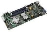
Platform Management Intel® Server Board X38ML 5.15 Processor Sensors The BMC provides IPMI sensors for processors and associated components, such as voltage regulators and fans. The sensors are implemented on a per-processor basis. Table 33. Processor Sensors Sensor Name Processor Status Digital Thermal Sensor Processor Voltage Description Processor presence and fault state Relative temperature reading via PECI Discrete sensor that indicates a processor power good state 5.15.1 Processor Status Sensors The BMC provides an IPMI sensor of type processor for monitoring status information for each processor slot. Except for the processor presence offset, if an event state (sensor offset) is asserted, it remains asserted until one of the following happens: ƒ A Rearm Sensor Events command is executed for the processor status sensor. ƒ AC or DC power cycle or system boot occurs. The BMC provides system status indication to the front panel LEDs for processor fault conditions shown in the table below. For more information refer to Section 5.7.2. Table 34. Processor Status Sensor Implementation Note: 1. Offset 0 1 2 3 4 5 6 7 8 9 Processor Status Internal error (IERR) Thermal trip FRB1/BIST failure FRB2/Hang in POST failure FRB3/Processor startup/initialization failure (CPU fails to start) Configuration error (for DMI) SM BIOS uncorrectable CPU-complex error Processor presence detected Processor disabled Terminator presence detected The fault is not reflected in the processor status sensor. Detected By BMC BMC Not Supported BIOS1 Not Supported BIOS Not Supported Not Supported BIOS Not Supported 5.15.1.1 ThermTrip Monitoring The BMC retains ThermTrip history for each processor. This history tracks whether the processor has had a ThermTrip since the last processor sensor re-arm or retest. When a ThermTrip occurs, the BMC polls the ThermTrip status for each processor and then the system begins the power down sequence. If the BMC detects a ThermTrip occurred, it sets the ThermTrip offset for the applicable processor status sensor. This ThermTrip data is not persistent across AC or DC cycles. 68 Revision 1.3 Intel order number E15331-006
-
 1
1 -
2
-
3
-
4
-
5
-
6
-
7
-
8
-
9
-
10
-
11
-
12
-
13
-
14
-
15
-
16
-
17
-
18
-
19
-
20
-
21
-
22
-
23
-
24
-
25
-
26
-
27
-
28
-
29
-
30
-
31
-
32
-
33
-
34
-
35
-
36
-
37
-
38
-
39
-
40
-
41
-
42
-
43
-
44
-
45
-
46
-
47
-
48
-
49
-
50
-
51
-
52
-
53
-
54
-
55
-
56
-
57
-
58
-
59
-
60
-
61
-
62
-
63
-
64
-
65
-
66
-
67
-
68
-
69
-
70
-
71
-
72
-
73
-
74
-
 75
75 -
 76
76 -
 77
77 -
 78
78 -
 79
79 -
 80
80 -
 81
81 -
 82
82 -
 83
83 -
 84
84 -
 85
85 -
86
-
87
-
88
-
89
-
90
-
91
-
92
-
93
-
94
-
95
-
96
-
97
-
98
-
99
-
100
-
101
-
102
-
103
-
104
-
105
-
106
-
107
-
108
-
109
-
110
-
111
-
112
-
113
-
114
-
115
-
116
-
117
-
118
-
119
-
120
-
121
-
122
-
123
-
124
-
125
-
126
-
127
-
128
-
129
-
130
-
131
-
132
 |
 |