Intel X38ML Product Specification - Page 63
Recovery Mode, OEM Logo
 |
UPC - 735858197397
View all Intel X38ML manuals
Add to My Manuals
Save this manual to your list of manuals |
Page 63 highlights
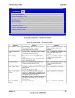
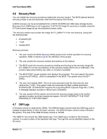
Intel® Server Board X38ML System BIOS 4.6 Recovery Mode You can initiate the recovery process by setting the recovery jumper. The BIOS detects that the recovery jumper is set and executes code from the backup boot blocks. A BIOS recovery can be accomplished from a SATA CD-ROM and USB mass storage device. Recovery from USB floppy is not supported. A SATA CD image for recovery is created using the El-Torito format image as per the published release notes. The recovery media must contain the image file FV_MAIN.FV in the root directory, along with the following files: ƒ IFLASH32.EFI ƒ *.CAP ƒ Update.NSH Recovery process: 1. The user moves the BIOS Recovery Mode jumper from normal operation to recovery operation. Refer to Section 7.8 for the definition of the jumper. 2. The user inserts the recovery medium and powers on the system. 3. The BIOS starts the recovery process by loading and booting to the recovery image file (FV_MAIN.FV) on the root directory of the recovery media (SATA CD or USB disk). This process takes place before any video or console is available. 4. The BIOS POST screen appears and displays the progress. The user selects the option to boot the EFI SHELL, which is embedded in the BIOS. The system boots the EFI SHELL. 5. The user runs Update.NSH. This is an auto-executed script file that uses the new capture file (*.CAP). The system loads and executes the flash update application, IFLASH32.EFI. IFLASH32.EFI requires the supporting BIOS Capsule image file (*.CAP). A message displays success or failure upon completion. 6. The user powers off the system and moves the recovery jumper back to the normal operation position and then restarts the system. DO NOT INTERRUPT THE POST PROCESS AT THE FIRST BOOT. 4.7 OEM Logo A firmware volume is reserved for OEMs. The OEM firmware volume holds the OEM logo and is updated independently of other firmware volumes. The OEM firmware volume hosts a firmware file system. The size of the OEM firmware volume is 128 KB. The OEM FV can include the OEM splash logo. If an OEM logo is located in the firmware volume, it is used in place of the standard Intel logo. The logo file can be identified based on the file name. Revision 1.3 51 Intel order number E15331-006
-
 1
1 -
2
-
3
-
4
-
5
-
6
-
7
-
8
-
9
-
10
-
11
-
12
-
13
-
14
-
15
-
16
-
17
-
18
-
19
-
20
-
21
-
22
-
23
-
24
-
25
-
26
-
27
-
28
-
29
-
30
-
31
-
32
-
33
-
34
-
35
-
36
-
37
-
38
-
39
-
40
-
41
-
42
-
43
-
44
-
45
-
46
-
47
-
48
-
49
-
50
-
51
-
52
-
53
-
54
-
55
-
56
-
57
-
 58
58 -
 59
59 -
 60
60 -
 61
61 -
 62
62 -
 63
63 -
 64
64 -
 65
65 -
 66
66 -
 67
67 -
 68
68 -
69
-
70
-
71
-
72
-
73
-
74
-
75
-
76
-
77
-
78
-
79
-
80
-
81
-
82
-
83
-
84
-
85
-
86
-
87
-
88
-
89
-
90
-
91
-
92
-
93
-
94
-
95
-
96
-
97
-
98
-
99
-
100
-
101
-
102
-
103
-
104
-
105
-
106
-
107
-
108
-
109
-
110
-
111
-
112
-
113
-
114
-
115
-
116
-
117
-
118
-
119
-
120
-
121
-
122
-
123
-
124
-
125
-
126
-
127
-
128
-
129
-
130
-
131
-
132
 |
 |