Intel X38ML Product Specification - Page 82
Fan Domains, Nominal Fan Speed
 |
UPC - 735858197397
View all Intel X38ML manuals
Add to My Manuals
Save this manual to your list of manuals |
Page 82 highlights
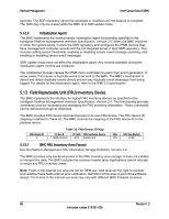
Platform Management Intel® Server Board X38ML used to manually force the fan domain speed to a selected value, overriding any other control or policy. The fan domain state is controlled by several factors. They are listed below in order of precedence, from high to low: ƒ Boost - An associated fan is in a critical state or missing. The reference document describes which fan domains are boosted in response to a fan failure or removal in each domain. - Any associated temperature sensor is in a critical state. The reference document describes which temperature threshold violations cause fan boost for each fan domain. - The chassis cover is missing. - If any of the above conditions apply, the fans are set to a fixed boost state speed, specified in the Tcontrol OEM SDRs. ƒ Sleep - No boost conditions, system in ACPI S1 sleep state. In this situation, fans are set to a fixed sleep state speed, specified in the Tcontrol OEM SDRs. The BMC can support normal fan speed control in the S1 sleep state, so the BIOS does not enable APCI fan control. ƒ Nominal - See Section 5.16.2. 5.16.1 Fan Domains System fan speeds are controlled through pulse width modulation (PWM) signals, which are driven separately for each domain by integrated PWM hardware. Fan speed is changed by adjusting the duty-cycle, which is the percentage of time the signal is driven high in each pulse. The BMC controls the average duty-cycle of each PWM signal through direct manipulation of the integrated PWM control registers. The same device may drive multiple PWM signals. For system-specific fan domains, see Table 35. Table 35. System Fan Domains Domain Location 0 System Fan 1 (refer to Figure 1 label 29.) 1 System Fan 2 (refer to Figure 1 label 30.) 2 System Fan 3 (refer to Figure 1 label 31.) Fans DIMM Fan Use for other chassis CPU blower Output PWM0 PWM1 PWM2 5.16.2 Nominal Fan Speed You can configure a fan domain's nominal fan speed as static (fixed value) or it can be controlled by the state of one or more associated temperature sensors. 70 Revision 1.3 Intel order number E15331-006
-
 1
1 -
2
-
3
-
4
-
5
-
6
-
7
-
8
-
9
-
10
-
11
-
12
-
13
-
14
-
15
-
16
-
17
-
18
-
19
-
20
-
21
-
22
-
23
-
24
-
25
-
26
-
27
-
28
-
29
-
30
-
31
-
32
-
33
-
34
-
35
-
36
-
37
-
38
-
39
-
40
-
41
-
42
-
43
-
44
-
45
-
46
-
47
-
48
-
49
-
50
-
51
-
52
-
53
-
54
-
55
-
56
-
57
-
58
-
59
-
60
-
61
-
62
-
63
-
64
-
65
-
66
-
67
-
68
-
69
-
70
-
71
-
72
-
73
-
74
-
75
-
76
-
 77
77 -
 78
78 -
 79
79 -
 80
80 -
 81
81 -
 82
82 -
 83
83 -
 84
84 -
 85
85 -
 86
86 -
 87
87 -
88
-
89
-
90
-
91
-
92
-
93
-
94
-
95
-
96
-
97
-
98
-
99
-
100
-
101
-
102
-
103
-
104
-
105
-
106
-
107
-
108
-
109
-
110
-
111
-
112
-
113
-
114
-
115
-
116
-
117
-
118
-
119
-
120
-
121
-
122
-
123
-
124
-
125
-
126
-
127
-
128
-
129
-
130
-
131
-
132
 |
 |