Mackie DL806 Reference Guide - Page 113
Gain Reduction Meter, Channel Faders and Input Meters, Selected Output Indicators
 |
View all Mackie DL806 manuals
Add to My Manuals
Save this manual to your list of manuals |
Page 113 highlights
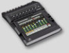
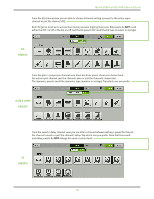
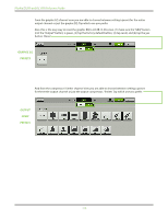
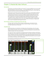
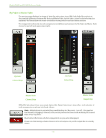
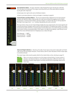
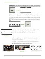
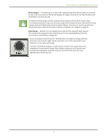
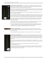
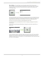
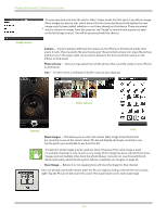
Mackie DL806 and DL1608 Reference Guide Gain Reduction Meter - The gain reduction meter displays the input channel gain reduction from the gate and compressor. The single meter shows the sum of the total reduction applied by the gate and compressor. It illuminates from right to left and is 20 dB when fully lit. To learn more about dynamics, check out chapter 10 starting on page 63. Channel Faders and Input Meters - The touch sensitive faders adjust the level of each channel going to the selected output. Adjustments are made by touching and dragging channel faders up and down. Touched channel faders will "grow & glow" to indicate that they are being adjusted. The fader level ranges from -∞ to +10 dB as indicated by the scale on the left. The input meters (next to each channel fader) display the input signal level to the channel before all channel processing. Changes made to the EQ, mute and fader do not affect these meters. This meter should remain green with the occasional bump into the yellow zone. Turn down the gain knob if the input meter remains consistently yellow. If the input is too high [overloading], a clip indicator at the top of the meter will illuminate red. If clipping occurs, reduce the gain. Red [clipping] = -3 dBFS Green to yellow = -18 dBFS Green [bottom] = -90 dBFS Selected Output Indicators - Directly to the right of each input meter (and underneath each fader cap) are the selected output indicators. These vary by color for clear indication of which output type is currently selected. The output type is discussed in greater detail in the master fader section, starting on page 44. There is no way you would ever see the image as shown below. It is just a point of reference. As mentioned above, each selected output has a different color for clear indication of which output type is currently selected. This is especially useful in the mixer view. LR AUX 1 AUX 2 AUX 3 AUX 4 AUX 5 AUX 6 REV DLY 113
-
 1
1 -
2
-
3
-
4
-
5
-
6
-
7
-
8
-
9
-
10
-
11
-
12
-
13
-
14
-
15
-
16
-
17
-
18
-
19
-
20
-
21
-
22
-
23
-
24
-
25
-
26
-
27
-
28
-
29
-
30
-
31
-
32
-
33
-
34
-
35
-
36
-
37
-
38
-
39
-
40
-
41
-
42
-
43
-
44
-
45
-
46
-
47
-
48
-
49
-
50
-
51
-
52
-
53
-
54
-
55
-
56
-
57
-
58
-
59
-
60
-
61
-
62
-
63
-
64
-
65
-
66
-
67
-
68
-
69
-
70
-
71
-
72
-
73
-
74
-
75
-
76
-
77
-
78
-
79
-
80
-
81
-
82
-
83
-
84
-
85
-
86
-
87
-
88
-
89
-
90
-
91
-
92
-
93
-
94
-
95
-
96
-
97
-
98
-
99
-
100
-
101
-
102
-
103
-
104
-
105
-
106
-
107
-
 108
108 -
 109
109 -
 110
110 -
 111
111 -
 112
112 -
 113
113 -
 114
114 -
 115
115 -
 116
116 -
 117
117 -
 118
118 -
119
-
120
-
121
-
122
-
123
-
124
-
125
-
126
-
127
-
128
-
129
-
130
-
131
-
132
-
133
-
134
-
135
-
136
-
137
-
138
-
139
-
140
-
141
-
142
-
143
-
144
-
145
-
146
-
147
-
148
-
149
-
150
-
151
-
152
-
153
-
154
-
155
-
156
-
157
-
158
-
159
-
160
 |
 |