Netgear FS728TPv2 FS728TP Software Administration Manual - Page 246
Policy Attribute: Simple Policy, Committed Burst Size: 128 KB
 |
View all Netgear FS728TPv2 manuals
Add to My Manuals
Save this manual to your list of manuals |
Page 246 highlights
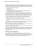
FS728TP Smart Switch Software Administration Manual 4. Click Apply. 5. From the Policy Configuration screen, create a new policy with the following settings: • Policy Selector: Policy1 • Member Class: Class1 For more information about this screen, see Policy Configuration on page 134. 6. Click Add to add the new policy. 7. Click the Policy1 hyperlink to view the Policy Class Configuration screen for this policy. 8. Configure the Policy attributes as follows: • Assign Queue: 3 • Policy Attribute: Simple Policy • Color Mode: Color Blind • Committed Rate: 1000000 Kbps • Committed Burst Size: 128 KB • Confirm Action: Send • Violate Action: Drop For more information about this screen, see Policy Configuration on page 134. 9. From the Service Configuration screen, select the check box next to interfaces g7 and g8 to attach the policy to these interfaces, and then click Apply (See Service Configuration on page 137). All UDP packet flows destined to the 192.12.2.0 network with an IP source address from the 192.12.1.0 network that have a Layer 4 Source port of 4567 and Destination port of 4568 from this switch on ports 7 and 8 are assigned to hardware queue 3. On this network, traffic from streaming applications uses UDP port 4567 as the source and 4568 as the destination. This real-time traffic is time sensitive, so it is assigned to a high-priority hardware queue. By default, data traffic uses hardware queue 0, which is designated as a best-effort queue. Also the confirmed action on this flow is to send the packets with a committed rate of 1000000 Kbps and burst size of 128 KB. Packets that violate the committed rate and burst size are dropped. 246 | Appendix B: Configuration Examples
-
 1
1 -
2
-
3
-
4
-
5
-
6
-
7
-
8
-
9
-
10
-
11
-
12
-
13
-
14
-
15
-
16
-
17
-
18
-
19
-
20
-
21
-
22
-
23
-
24
-
25
-
26
-
27
-
28
-
29
-
30
-
31
-
32
-
33
-
34
-
35
-
36
-
37
-
38
-
39
-
40
-
41
-
42
-
43
-
44
-
45
-
46
-
47
-
48
-
49
-
50
-
51
-
52
-
53
-
54
-
55
-
56
-
57
-
58
-
59
-
60
-
61
-
62
-
63
-
64
-
65
-
66
-
67
-
68
-
69
-
70
-
71
-
72
-
73
-
74
-
75
-
76
-
77
-
78
-
79
-
80
-
81
-
82
-
83
-
84
-
85
-
86
-
87
-
88
-
89
-
90
-
91
-
92
-
93
-
94
-
95
-
96
-
97
-
98
-
99
-
100
-
101
-
102
-
103
-
104
-
105
-
106
-
107
-
108
-
109
-
110
-
111
-
112
-
113
-
114
-
115
-
116
-
117
-
118
-
119
-
120
-
121
-
122
-
123
-
124
-
125
-
126
-
127
-
128
-
129
-
130
-
131
-
132
-
133
-
134
-
135
-
136
-
137
-
138
-
139
-
140
-
141
-
142
-
143
-
144
-
145
-
146
-
147
-
148
-
149
-
150
-
151
-
152
-
153
-
154
-
155
-
156
-
157
-
158
-
159
-
160
-
161
-
162
-
163
-
164
-
165
-
166
-
167
-
168
-
169
-
170
-
171
-
172
-
173
-
174
-
175
-
176
-
177
-
178
-
179
-
180
-
181
-
182
-
183
-
184
-
185
-
186
-
187
-
188
-
189
-
190
-
191
-
192
-
193
-
194
-
195
-
196
-
197
-
198
-
199
-
200
-
201
-
202
-
203
-
204
-
205
-
206
-
207
-
208
-
209
-
210
-
211
-
212
-
213
-
214
-
215
-
216
-
217
-
218
-
219
-
220
-
221
-
222
-
223
-
224
-
225
-
226
-
227
-
228
-
229
-
230
-
231
-
232
-
233
-
234
-
235
-
236
-
237
-
238
-
239
-
240
-
 241
241 -
 242
242 -
 243
243 -
 244
244 -
 245
245 -
 246
246 -
 247
247 -
 248
248 -
 249
249 -
 250
250 -
 251
251 -
252
-
253
-
254
-
255
-
256
-
257
-
258
-
259
-
260
-
261
 |
 |
