Netgear GS724AT GS724AT Reference Manual
Netgear GS724AT - ProSafe Gigabit Smart Switch Manual
 |
UPC - 606449056907
View all Netgear GS724AT manuals
Add to My Manuals
Save this manual to your list of manuals |
Netgear GS724AT manual content summary:
- Netgear GS724AT | GS724AT Reference Manual - Page 1
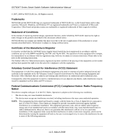
GS700AT Series Smart Switch Software Administration Manual NETGEAR, Inc. 4500 Great America Parkway Santa Clara, CA 95054 USA 202-10360-01 March 2008 - Netgear GS724AT | GS724AT Reference Manual - Page 2
Switch Software Administration Manual © 2007, 2008 by NETGEAR, Inc. All Rights reserved. Trademarks NETGEAR and the NETGEAR logo are registered trademarks of NETGEAR restrictions. Please refer to the notes in the operating instructions. The Federal Office for Telecommunications Approvals has been - Netgear GS724AT | GS724AT Reference Manual - Page 3
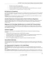
du Canada. Customer Support For assistance with installing and configuring your NETGEAR system or for questions or problems following installation: • Check the NETGEAR Web page at http://www.NETGEAR.com/support • Call Technical Support in North America at 1-888-NETGEAR. If you are outside - Netgear GS724AT | GS724AT Reference Manual - Page 4
GS700AT Series Smart Switch Software Administration Manual the radiator and your body. This transmitter must not be co-located or operating in conjunction with any other antenna or transmitter. FCC Declaration Of Conformity: We, NETGEAR, Inc., 4500 Great America Parkway, Santa Clara, CA 95054, - Netgear GS724AT | GS724AT Reference Manual - Page 5
to the Web Browser Interface Logging Into the NETGEAR Home Screen 2-1 Using the NETGEAR Web Management System Options 2-3 Chapter 3 Managing System Settings Using the System Settings Utility 3-1 Management ...3-1 Device View ...3-7 SNMP ...3-7 LLDP ...3-27 Chapter 4 Configuring Switching Settings - Netgear GS724AT | GS724AT Reference Manual - Page 6
GS700AT Series Smart Switch Software Administration Manual Ports ...4-1 LAG ...4-4 VLAN ...4-14 Voice VLAN ...4-22 STP ...4-28 Multicast ...4-38 Address Table ...4-47 Chapter 5 Configuring QoS Configuring the Basic and Advanced QoS Settings 5-1 CoS ...5-1 Chapter 6 Managing Security Setting - Netgear GS724AT | GS724AT Reference Manual - Page 7
Smart Switch Software Administration Manual Support ...9-1 User Guide ...9-2 Appendix A Default Settings Index Contents vii v1.0, December 2007 - Netgear GS724AT | GS724AT Reference Manual - Page 8
GS700AT Series Smart Switch Software Administration Manual viii Contents v1.0, December 2007 - Netgear GS724AT | GS724AT Reference Manual - Page 9
Once basic configuration is performed, the switch operates using the remaining factory default parameters. However, a greater level of configuration-anywhere from the basic up to the maximum possible-will allow your network the full benefit of the switch's features. The web interface simplifies this - Netgear GS724AT | GS724AT Reference Manual - Page 10
how to configure switch monitoring. • Chapter 8, "Maintenance" describes the firmware upgrade procedure and reset functions. • Chapter 9, "Online Help" describes how to obtain online help and support. • Appendix A, "Default Settings" gives GS700AT Series Smart Switch specifications and lists - Netgear GS724AT | GS724AT Reference Manual - Page 11
the GS700AT Series Smart Switch according to these specifications: Product Version Manual Publication Date GS700AT Gigabit Smart Switch March 2008 . Note: Product updates are available on the NETGEAR, Inc. website at http://www.netgear.com/support. How to Use This Manual The HTML version of - Netgear GS724AT | GS724AT Reference Manual - Page 12
a PDF version of the Complete Manual. • Click the Complete PDF Manual link at the top left of any page in the manual. The PDF version of the complete manual opens in a browser window. • Click the print icon in the upper left of your browser window. Tip: If your printer supports printing two pages on - Netgear GS724AT | GS724AT Reference Manual - Page 13
GS700AT Series Smart Switch Software Administration Manual xiii v1.0, March 2008 - Netgear GS724AT | GS724AT Reference Manual - Page 14
in this manual: • Network facilities: - Ethernet network with or without DHCP server as appropriate - Ethernet cable to connect the switch to a PC • For running the SmartWizard Discovery utility and local or remote Web Management: - IBM-type PC with CD drive: RAM size and disk specification are not - Netgear GS724AT | GS724AT Reference Manual - Page 15
Manual Note: For complete hardware installation instructions, refer to the GS700AT Series Smart Switch Hardware Installation Manual included on your Resource CD, or go to http://www.netgear.com/support. Switch Management Interface Your NETGEAR GS700AT Gigabit Smart Switch contains an embedded web - Netgear GS724AT | GS724AT Reference Manual - Page 16
Web browser interface No IP address or subnet mask setup needed Discover all switches on the network User-friendly interface under Microsoft Windows Firmware upgrade capability Password change feature Provides entry to web configuration of switch Password protection Ideal for configuring the switch - Netgear GS724AT | GS724AT Reference Manual - Page 17
1-1 6. Note the displayed IP address assigned by the DHCP server. You will need this value to access the switch directly from a web browser (without using the SmartWizard Discovery utility). 7. Select your switch by highlighting the name of the switch. Then click Web Access. The discovery utility - Netgear GS724AT | GS724AT Reference Manual - Page 18
for your switch • Configure the NIC settings on the host PC • Log in to the web-based switch management utility Manually Assigning Network Parameters If your network has no DHCP service, you must assign a static IP address to your switch. You can also assign the switch a static IP address even if - Netgear GS724AT | GS724AT Reference Manual - Page 19
Manual 6. Click Configuration Setting. A screen similar to that shown below appears. Figure 1-3 7. Select Disable to disable DHCP. 8. The default IP address is 192.168.0.239 and the default subnet mask is 255.255.255.0. If you want different values, enter the switch IP address, gateway IP address - Netgear GS724AT | GS724AT Reference Manual - Page 20
Smart Switch Software Administration Manual NIC Setting on the Host that Accesses the GS700AT Gigabit Smart Switch The settings of your Network Interface Card that set in the switch. The PC IP address must be different from that of the switch but lie in the same subnet. 3. Click Web Access in the - Netgear GS724AT | GS724AT Reference Manual - Page 21
, use that IP address in your browser window. If you are starting with an "out of the box" switch and are not using the SmartWizard Discovery utility, you must initially configure your host PC to be on a network segment to match the default parameters of the switch, which are: • IP address: 192.168 - Netgear GS724AT | GS724AT Reference Manual - Page 22
new password. Firmware Upgrade The GS700AT Series Smart Switch software is upgradeable, and enables your switch to take advantage of improvements and additional features as they become available. The upgrade procedure assumes that you have downloaded or otherwise obtained the firmware upgrade and - Netgear GS724AT | GS724AT Reference Manual - Page 23
: • Product Assigned Firmware: The location of the new firmware. If you do not know the location, click Browse to locate the file. • Upgrade Password: Enter your password; the default password is password. 2. Click Apply to apply the settings to the Upgrade Configuration. 3. Click Start Upgrade to - Netgear GS724AT | GS724AT Reference Manual - Page 24
Introduction to the Web Browser Interface This section introduces the web browser interface that enables you to configure and manage your NETGEAR GS700AT Gigabit Smart Switch. Your GS700AT Series Smart Switch provides a built-in browser interface that enables you to configure and manage it remotely - Netgear GS724AT | GS724AT Reference Manual - Page 25
Administration Manual 2. Enter the password (the factory default is password) and click Login. The home screen of the GS700AT Series Smart Switch browser interface displays. The Navigation Menu As shown below, logging in brings you to the view of the web browser interface. Figure 2-2 The NETGEAR - Netgear GS724AT | GS724AT Reference Manual - Page 26
services including technical support, online help and device information. • Using Screen and Table Options - Provides an explanation of specific GUI characteristics and tables for configuring the device. Device Management Buttons The NETGEAR GS700AT Series Smart Switch web browser GUI - Netgear GS724AT | GS724AT Reference Manual - Page 27
services including NETGEAR online support and an online user guide in PDF format. For a detailed description of how to access and use these functions, see Chapter 9, "Online Help". Accessing Device Information Each screen of the web browser interface contains a help file with configuration - Netgear GS724AT | GS724AT Reference Manual - Page 28
Smart Switch Software Administration Manual To access the help file for a screen: 1. Click the encircled red Question Mark icon, shown in the example below. Figure 2-3 A help window for the screen opens. Figure 2-4 Using Screen and Table Options The NETGEAR GS700AT Series web browser interface - Netgear GS724AT | GS724AT Reference Manual - Page 29
GS700AT Series Smart Switch Software Administration Manual Selecting an Entry To select an entry: 1. Check the entry's Select box. The selected entry is added to the table by creating a new entry or by duplicating an existing entry. 2-6 Introduction to the Web Browser Interface v1.0, March 2008 - Netgear GS724AT | GS724AT Reference Manual - Page 30
GS700AT Series Smart Switch Software Administration Manual To add an entry by creating a new entry in the table: 1. Enter the fields for the new . Figure 2-9 2. Modify the fields in the first row. 3. Click APPLY to update the device. Introduction to the Web Browser Interface 2-7 v1.0, March 2008 - Netgear GS724AT | GS724AT Reference Manual - Page 31
device. Special Table Options The NETGEAR web browser interface tables have a unique GUI design which includes the following options: • Gold Buttons • Quick Boxes • Interface View and Selection Gold Buttons. Gold Buttons provide flexibility in viewing and configuring VLANs/LAGs on a port level. The - Netgear GS724AT | GS724AT Reference Manual - Page 32
GS700AT Series Smart Switch Software Administration Manual To mark or unmark all ports: 1. Click on the quick box that appears to the left of the Port all the port boxes appear blank, marking the ports as neither tagged nor untagged. Introduction to the Web Browser Interface 2-9 v1.0, March 2008 - Netgear GS724AT | GS724AT Reference Manual - Page 33
GS700AT Series Smart Switch Software Administration Manual 5. You may click on individual port boxes to toggle their tagged/untagged status Interface View and Selection. A port or LAG interface may be selected from a table by using the interface selection row, located above the row of column headers - Netgear GS724AT | GS724AT Reference Manual - Page 34
Series Smart Switch Software Administration Manual 3. Click OK. The screen displays a table of all interfaces. To display the LAG table: 1. Click LAGS in the interface selection row. The screen displays a table of all LAGs. Figure 2-16 To select an interface: 1. Enter the number of the interface in - Netgear GS724AT | GS724AT Reference Manual - Page 35
GS700AT Series Smart Switch Software Administration Manual 2-12 Introduction to the Web Browser Interface v1.0, March 2008 - Netgear GS724AT | GS724AT Reference Manual - Page 36
of the web browser interface contains a System tab that enables you to manage your GS700AT Series Smart Switch with features under the following main menu options: • "Management" • "Device View" • "SNMP" • "LLDP" The description that follows in this chapter describes configuring and managing system - Netgear GS724AT | GS724AT Reference Manual - Page 37
Smart Switch Software Administration Manual To configure system - Displays the amount of time since the most recent device reset. The system time is displayed in the following format: days, 30 minutes. The field default value is 10 minutes. • Base MAC Address - Displays the MAC address of . • Serial - Netgear GS724AT | GS724AT Reference Manual - Page 38
disable Jumbo Frames After Reset. 4. Click Apply to update the system settings. IP Configuration The IP Configuration screen contains fields for assigning IP addresses. IP addresses are either defined as static or are retrieved using the Dynamic Host Configuration Protocol (DHCP). The IP Interface - Netgear GS724AT | GS724AT Reference Manual - Page 39
Series Smart Switch Software Administration Manual To define an IP interface: 1. Click System > Management > IP Configuration. The IP Configuration screen displays: Figure 3-2 The IP Configuration screen contains the following fields: • Dynamic IP Address (DHCP) - Enable the IP address to be - Netgear GS724AT | GS724AT Reference Manual - Page 40
GS700AT Series Smart Switch Software Administration Manual Time Configuration The Time Configuration screen contains information for defining both the local hardware clock and the external SNTP clock. If the system time is managed via an external SNTP - Netgear GS724AT | GS724AT Reference Manual - Page 41
GS700AT Series Smart Switch Software Administration Manual 5. Click Apply to update the system settings. Note: If you selected SNTP, you must configure the SNTP servers. See "SNTP Server Configuration" for detailed instructions on configuring the SNTP servers. SNTP Server Configuration The SNTP - Netgear GS724AT | GS724AT Reference Manual - Page 42
Smart Switch Software Administration Manual To SNMP) provides a method for managing network devices. The device supports the following SNMP versions: • SNMP v1 and v2c • Management Information Base (MIB). The SNMP agent defines the MIB specification format, as well as the format used to access the - Netgear GS724AT | GS724AT Reference Manual - Page 43
Switch Software Administration Manual by the system to manage device features. SNMP v3 supports the following features: • Security • Feature Access Control Configuration" • "Trap Configuration" Community Configuration Access rights are managed by defining communities in the Community Configuration - Netgear GS724AT | GS724AT Reference Manual - Page 44
Manual To configure SNMP communities: 1. Click System > SNMP > SNMPv1/v2 > Community Configuration. The Community Configuration screen displays: Figure 3-6 The SNMPv1/v2 Community Configuration screen contains the following fields: • Management Station - Enter the management station IP address - Netgear GS724AT | GS724AT Reference Manual - Page 45
station management: 1. Click System > SNMP > SNMPv1/v2 > Trap Configuration. The SNMPv1/v2 Trap Configuration screen displays: Figure 3-7 The SNMPv1/v2 Trap Configuration screen contains the following fields: • Recipients IP - Enter the IP address to which the traps are sent. 3-10 v1.0, March - Netgear GS724AT | GS724AT Reference Manual - Page 46
GS700AT Series Smart Switch Software Administration Manual • Notification Type - (Configurable only if the Notification Version is sent. • UDP Port - Enter the UDP port used to send notifications. The default UDP port is 162. • Timeout - Enter the amount of time (in seconds) the device - Netgear GS724AT | GS724AT Reference Manual - Page 47
GS700AT Series Smart Switch Software Administration Manual • "View Name" • "View Content" • "Community Configuration" • "Group Configuration" • "User Configuration" • "Global Trap Configuration" • "Trap Configuration" • "Trap Filter Name" • "Trap Filter Content" Engine ID The SNMPv3 Engine ID screen - Netgear GS724AT | GS724AT Reference Manual - Page 48
GS700AT Series Smart Switch Software Administration Manual • Use Default - Check the box to use the device-generated Engine ID. The default Engine ID is based on the device MAC address and is defined per standard as: - First 4 octets - First bit = 1, the rest is the IANA Enterprise number. - Fifth - Netgear GS724AT | GS724AT Reference Manual - Page 49
GS700AT Series Smart Switch Software Administration Manual To add a new SNMP View Name: 1. Click System > SNMP > SNMPv3 > View Name. The SNMPv3 View Name screen displays. 2. Enter the View Name field in the - Netgear GS724AT | GS724AT Reference Manual - Page 50
GS700AT Series Smart Switch Software Administration Manual • Object ID Subtree - Enter the device feature OID. 4. Click Delete to remove the entry. Community Configuration Access rights are managed by defining communities in the Community Configuration screen. When community names are changed, access - Netgear GS724AT | GS724AT Reference Manual - Page 51
screen displays: Figure 3-11 The SNMPv3 Community Configuration screen contains the following fields: • Management Station - Enter the management station IP address for which the SNMP community is defined. • Community String - Enter the password used to authenticate the management station to the - Netgear GS724AT | GS724AT Reference Manual - Page 52
access control privileges to SNMP groups. Groups allow network managers to assign access rights to specific device features or feature aspects. To define an SNMP group: 1. Click System > SNMP > SNMPv3 > Group Configuration. The SNMPv3 Groups screen displays: Figure 3-12 The SNMPv3 Groups screen - Netgear GS724AT | GS724AT Reference Manual - Page 53
Switch Software Administration Manual • Security Level - Select the security level attached to the group. Security levels apply to SNMPv3 only. The possible field values are: - No Authentication - Neither the Authentication nor the Privacy security levels are assigned > Group Configuration. The - Netgear GS724AT | GS724AT Reference Manual - Page 54
Series Smart Switch Software Administration Manual 3. Click Delete to remove the entry. User Configuration The SNMPv3 User Configuration screen provides information for creating SNMP groups and assigning SNMP access control privileges to SNMP groups. Groups allow network managers to assign access - Netgear GS724AT | GS724AT Reference Manual - Page 55
Switch Software Administration Manual - SHA Password - Users are authenticated using the HMAC-SHA-96 authentication level. The user must enter a password. - None - No user authentication is used. • Password (1-32 Characters) - Enter the password Users Configuration. The SNMPv3 User Configuration - Netgear GS724AT | GS724AT Reference Manual - Page 56
GS700AT Series Smart Switch Software Administration Manual To remove an SNMPv3 user: 1. Click System > SNMP > SNMPv3 > Users Configuration. The SNMPv3 User Configuration screen displays. 2. Select the user entry. 3. Click Delete to remove the entry. Global Trap Configuration The SNMPv3 Global Trap - Netgear GS724AT | GS724AT Reference Manual - Page 57
trap station management: 1. Click System > SNMP > SNMPv3 > Trap Configuration. The SNMPv3 Trap Configuration screen displays: Figure 3-15 The SNMPv3 Trap Configuration screen contains the following fields: • Recipients IP - Enter the IP address to which the traps are sent. • Notification Type - Netgear GS724AT | GS724AT Reference Manual - Page 58
Smart Switch Software Administration Manual - Authentication nor the Privacy security levels are assigned to the group. - Authentication - Authenticates SNMP > SNMPv3 > Trap Configuration. The SNMPv3 Trap Configuration screen displays. 2. Enter the Recipients IP address in the provided field in - Netgear GS724AT | GS724AT Reference Manual - Page 59
GS700AT Series Smart Switch Software Administration Manual 6. Enter the UDP Port in the provided Configuration screen displays. 2. Select the trap entry. 3. Click Delete to remove the entry. Trap Filter Name The SNMPv3 Trap Filter Name screen permits filtering traps based on OIDs. Each OID is linked - Netgear GS724AT | GS724AT Reference Manual - Page 60
GS700AT Series Smart Switch Software Administration Manual 3. Enter the trap Filter Name in the provided field in the Content The SNMPv3 Trap Filter Content screen permits filtering traps based on OIDs. Each OID is linked to a device feature or a portion of a feature. The SNMPv3 Trap Filter Content - Netgear GS724AT | GS724AT Reference Manual - Page 61
GS700AT Series Smart Switch Software Administration Manual Trap Filter Settings • Filter Name - Select the user-defined notification filter from the list. Trap Filter Settings • Object ID Subtree - Enter the OID for which - Netgear GS724AT | GS724AT Reference Manual - Page 62
Switch Software Administration Manual The Link Layer Discovery Protocol (LLDP) allows network managers to troubleshoot and contains the following option: • "LLDP Configuration" LLDP Configuration The Basic LLDP Configuration screen allows network managers to assign global LLDP and LLDP-MED (LLDP - Netgear GS724AT | GS724AT Reference Manual - Page 63
Switch Software Administration Manual To configure LLDP settings: 1. Click System > LLDP > Basic > LLDP Configuration. The Basic LLDP Configuration screen displays: Figure 3-18 The Basic LLDP Configuration possible field range is 2 - 10. The field default is 4. For example, if the TLV Advertised - Netgear GS724AT | GS724AT Reference Manual - Page 64
GS700AT Series Smart Switch Software Administration Manual • Reinitializing Delay - Enter the amount of time in seconds that passes between disabling and reinitializing LLDP. The possible field range is 1 - 10 seconds. The field default is 2 seconds. • Transmit Delay - Enter the amount of time in - Netgear GS724AT | GS724AT Reference Manual - Page 65
Switch Software Administration Manual To configure LLDP settings: 1. Click System > LLDP > Advanced > LLDP Configuration. The Advanced LLDP Configuration screen displays: Figure 3-19 The Advanced LLDP Configuration field range is 2 - 10. The field default is 4. For example, if the TLV Advertised - Netgear GS724AT | GS724AT Reference Manual - Page 66
GS700AT Series Smart Switch Software Administration Manual • Reinitializing Delay - Enter the amount of time in seconds that passes between disabling and reinitializing LLDP. The possible field range is 1 - 10 seconds. The field default is 2 seconds. • Transmit Delay - Enter the amount of time in - Netgear GS724AT | GS724AT Reference Manual - Page 67
Smart Switch Software Administration Manual To define LLDP Port Properties: 1. Click System > LLDP > Advanced > LLDP Port Settings. The LLDP Port Settings screen displays: Figure 3-20 The LLDP Port Settings screen contains the following fields: • Interface - Displays the specific interface for - Netgear GS724AT | GS724AT Reference Manual - Page 68
what software is running on what switch, and what port is connected to what PC. • Automatically deploys policies over networks for: - QoS Policies - Voice VLANs • Provides Emergency Call Service (E-911) via IP Phone location information. • Provides troubleshooting information. LLDP-MED sends network - Netgear GS724AT | GS724AT Reference Manual - Page 69
GS700AT Series Smart Switch Software Administration Manual The LLDP-MED Network Policy screen allows network administrators to define LLDP-MED network policies, which include the application, VLAN ID, VLAN type, user priority and DSCP value. To configure LLDP-MED Network Policy: 1. Click System > - Netgear GS724AT | GS724AT Reference Manual - Page 70
• DSCP Value - Select the DSCP value assigned to the network policy. The possible field value is 0 - 63. 2. Select the Network Policy entry to configure. 3. Select the Network Policy Number from the list in the provided field in the first row. 4. Enter the VLAN ID in the provided field in the first - Netgear GS724AT | GS724AT Reference Manual - Page 71
GS700AT Series Smart Switch Software Administration Manual LLDP-MED Port Settings The LLDP-MED Port Settings screen contains parameters for assigning LLDP-MED network policies to specific ports. To configure LLDP-MED port settings: 1. Click System > LLDP > Advanced > LLDP-MED Port Settings. The LLDP - Netgear GS724AT | GS724AT Reference Manual - Page 72
GS700AT Series Smart Switch Software Administration Manual 4. Select the Notification Status of the selected port from chassis ID type. For example, MAC address. • Chassis ID - Displays the chassis identification of the device transmitting the LLDP frame. Managing System Settings v1.0, March 2008 - Netgear GS724AT | GS724AT Reference Manual - Page 73
Smart Switch Software Administration Manual • System Name - Displays the administratively assigned device Interface - Displays the port number. • Port ID Subtype - Displays the port ID type. For example, MAC address. • Port ID - Displays the port identification of the port transmitting the LLDP frame - Netgear GS724AT | GS724AT Reference Manual - Page 74
GS700AT Series Smart Switch Software Administration Manual 2. Click the Interface to view its detailed information. The Port Information window opens: Figure 3-24 The Port Information window contains the following fields: Managed Address • Address Subtype - Displays the managed address subtype. For - Netgear GS724AT | GS724AT Reference Manual - Page 75
Smart Switch Software Administration Manual - interfaces' collision detection and bit injection into the network. For example, 100BASE-TX full duplex mode. MED Details • Capabilities Supported Voice. • VLAN ID - Displays the network policy VLAN ID. • VLAN Type - Displays the VLAN type for which - Netgear GS724AT | GS724AT Reference Manual - Page 76
GS700AT Series Smart Switch Software Administration Manual To view LLDP neighbors information: 1. Click System > LLDP For example, MAC address. • Port ID - Displays the port identification of the port transmitting the LLDP frame. • System Name - Displays the administratively assigned device name. 2. - Netgear GS724AT | GS724AT Reference Manual - Page 77
GS700AT Series Smart Switch Software Administration Manual 2. Click the MSAP Entry to view its detailed information. The Neighbors Information window opens: Figure 3-26 3-42 v1.0, March 2008 Managing System Settings - Netgear GS724AT | GS724AT Reference Manual - Page 78
For example, MAC or IPv4. • Address - Displays the managed address. • Interface Subtype - Displays the port subtype. • Interface Number - Displays the port number. MAC/PHY Details • Auto-Negotiation Supported - Displays the port speed auto-negotiation support status. The possible values are: - True - Netgear GS724AT | GS724AT Reference Manual - Page 79
basic LLDP services. - Endpoint Class 2 - Indicates a media endpoint class, offering media streaming capabilities as well as all Class 1 features. - Endpoint Class 3 - Indicates a communications device class, offering all Class 1 and Class 2 features plus location, 911, Layer 2 switch support and - Netgear GS724AT | GS724AT Reference Manual - Page 80
GS700AT Series Smart Switch Software Administration Manual Location Information • Civic - Displays the device's civic or street address location. For example, 123 45th St E. The field value length range is 6 - 160 characters. • Coordinates - Displays the device's location map coordinates - latitude, - Netgear GS724AT | GS724AT Reference Manual - Page 81
GS700AT Series Smart Switch Software Administration Manual 3-46 v1.0, March 2008 Managing System Settings - Netgear GS724AT | GS724AT Reference Manual - Page 82
Configuring Switching Settings The navigation pane at the top of the web browser interface contains a Switching tab that enables you to manage your GS700AT Series Smart Switch with features under the following main headings: • "Ports" • "LAG" • "VLAN" • "Voice VLAN" • "STP" • "Multicast" • "Address - Netgear GS724AT | GS724AT Reference Manual - Page 83
GS700AT Series Smart Switch Software Administration Manual To configure port parameters: 1. Click Switching > Ports > Port Configuration. The Port Configuration screen displays: Figure 4-1 The Port Configuration screen contains the following fields: • Port - Displays the port number. • Port - Netgear GS724AT | GS724AT Reference Manual - Page 84
configurable only when auto negotiation is disabled and the port speed is set to 10M or 100M. The possible field values are: - Half - The interface supports by default. The possible field values are: - Enable - Enable flow control. - Disable - Disable Flow control. Configuring Switching Settings - Netgear GS724AT | GS724AT Reference Manual - Page 85
) - Connect HUBs and switches. • LAG ID - Select the LAG ID to which the selected port is assigned. 2. Select the interface. 3. Enter or modify the fields in the first row. 4. Click Apply to update the device. LAG A Link Aggregated Group (LAG) optimizes port usage by linking a group of ports - Netgear GS724AT | GS724AT Reference Manual - Page 86
Switch Software Administration Manual • LACP LAGs support up to 16 ports, with eight ports active at any given time. The LAG menu contains the following options: • "Basic" • "Advanced" Basic The LAG Basic menu contains the following options: • "LAG Configuration" • "LAG Membership" LAG Configuration - Netgear GS724AT | GS724AT Reference Manual - Page 87
LAG is in full duplex mode. Flow Control is disabled by default. The possible field values are: - Enable - Enable flow control. - Disable - Disable flow control. 2. Select the interface. 3. Enter or modify the fields in the first row. 4. Click Apply to update the device. 4-6 Configuring Switching - Netgear GS724AT | GS724AT Reference Manual - Page 88
- Static - The LAG is configured manually. - LACP - The LAG is configured dynamically. 2. Select the LAG ID and LAG Type. 3. Click on the gold button. The port panel displays. 4. Select the ports to be members of the LAG. 5. Click Apply to update the device. Configuring Switching Settings 4-7 v1 - Netgear GS724AT | GS724AT Reference Manual - Page 89
• "LAG Configuration" • "LAG Membership" • "LACP Configuration" • "LACP Port Configuration" LAG Configuration The Advanced LAG Configuration screen contains fields for configuring LAG parameters. The system supports 8 LAGs, and each LAG can contain up to 8 ports. 4-8 Configuring Switching Settings - Netgear GS724AT | GS724AT Reference Manual - Page 90
Series Smart Switch Software Administration Manual To define LAG parameters: 1. Click Switching > LAG > Advanced > LAG Configuration. The Advanced LAG Configuration screen displays: Figure 4-5 The Advanced LAG Configuration screen contains the following fields: • Interface - Displays the LAG number - Netgear GS724AT | GS724AT Reference Manual - Page 91
Flow Control is disabled by default. The possible field values are: - Enable - Enable flow control. - Disable - Disable flow control. 2. Select the interface. 3. Enter or modify the fields in the first row. 4. Click Apply to update the device. 4-10 v1.0, March 2008 Configuring Switching Settings - Netgear GS724AT | GS724AT Reference Manual - Page 92
: - Static - The LAG is configured manually. - LACP - The LAG is configured automatically. 2. Select the LAG ID and LAG Type. 3. Click on the gold button. The port panel displays. 4. Select the ports to be members of the LAG. 5. Click Apply to update the device. Configuring Switching Settings v1 - Netgear GS724AT | GS724AT Reference Manual - Page 93
links. Aggregated ports can be linked into link-aggregation port-groups. Each group is comprised of ports with the same speed. The LACP Configuration screen contains fields for configuring LACP. To configure LACP: 1. Click Switching > LAG > Advanced > LACP Configuration. The LACP Configuration - Netgear GS724AT | GS724AT Reference Manual - Page 94
: 1. Click Switching > LAG > Advanced > LACP Port Configuration. The LACP Port Configuration screen displays: Figure 4-9 The LACP Port Configuration screen contains the following fields: • Interface - Displays the interface number to which timeout and priority values are assigned. • LACP Priority - Netgear GS724AT | GS724AT Reference Manual - Page 95
GS700AT Series Smart Switch Software Administration Manual - Short - A short timeout value (3 seconds). 2. Select the interface. 3. Enter the LACP Priority and select the Timeout in the provided fields in the first row. 4. Click Apply to update the device. VLAN VLANs are logical subgroups with a - Netgear GS724AT | GS724AT Reference Manual - Page 96
Manual VLAN Configuration The Basic VLAN Configuration screen provides information and parameters for configuring and working with VLANs. The maximum number of active VLANs is 128. To define VLAN properties: 1. Click Switching > VLAN > Basic > VLAN Configuration. The Basic VLAN Configuration - Netgear GS724AT | GS724AT Reference Manual - Page 97
Administration Manual To remove a VLAN: 1. Click Switching > VLAN > Basic > VLAN Configuration. The Basic VLAN Configuration screen displays. 2. Select the VLAN entry. 3. Click Delete to remove the entry. Advanced The VLAN Advanced menu contains the following options: • "VLAN Configuration" • "VLAN - Netgear GS724AT | GS724AT Reference Manual - Page 98
VLAN is the default VLAN. The default VLAN is enabled by default. 2. Select the VLAN entry. 3. Enter the VLAN ID and VLAN Name in the provided fields in the first row. 4. Click Apply to update the device. To add a new VLAN: 1. Click Switching > VLAN > Advanced > VLAN Configuration. The Advanced VLAN - Netgear GS724AT | GS724AT Reference Manual - Page 99
Software Administration Manual To define VLAN group membership: 1. Click Switching > VLAN > Advanced > VLAN Membership. The VLAN Membership screen displays: Figure 4-12 The VLAN Membership screen contains the following fields: • VLAN ID - Select the VLAN ID to be displayed and configured. VLAN ID - Netgear GS724AT | GS724AT Reference Manual - Page 100
or LAGs as tagged or untagged, respectively. 3. Click Apply to update the device. To view VLAN tagged port members: 1. Click Switching > VLAN > Advanced > VLAN Membership. The VLAN Membership screen displays. 2. Click TAGGED PORT MEMBERS. The VLAN Tagged Ports window opens: Figure 4-13 Configuring - Netgear GS724AT | GS724AT Reference Manual - Page 101
is configured the default VLAN PVID is used. VLAN ID 1 belongs to the default VLAN which cannot be deleted from the system. Once the PVID is changed from 1 to another VLAN ID on an interface, the default VLAN on that interface is automatically removed. 4-20 v1.0, March 2008 Configuring Switching - Netgear GS724AT | GS724AT Reference Manual - Page 102
: 1. Click Switching > VLAN > Advanced > Port PVID Configuration. The Port PVID Configuration screen displays: Figure 4-15 The Port PVID Configuration screen contains the following fields: • Interface - Displays the interface id (port number or LAG number) to which the PVID tag is assigned. • PVID - Netgear GS724AT | GS724AT Reference Manual - Page 103
Series Smart Switch Software Administration Manual Voice VLAN Voice VLAN allows you to enhance VoIP service by configuring ports to carry IP voice traffic from IP phones on a specific VLAN. VoIP traffic has a preconfigured OUI prefix in the source MAC address. You can configure VLANs on which - Netgear GS724AT | GS724AT Reference Manual - Page 104
The field format is Day, Hour, Minute. The aging time starts after the MAC Address is aged out from the Dynamic MAC Address table. The default time is 300 sec. For more information on defining MAC address age out time, see "Dynamic Addresses". Configuring Switching Settings v1.0, March 2008 4-23 - Netgear GS724AT | GS724AT Reference Manual - Page 105
contains the following fields: • VoiceVLAN Status - Select the Voice VLAN status on the device. The possible field values are: - Enable - Enable Voice VLAN on the device. - Disable - Disable Voice VLAN on the device. This is the default value. 4-24 v1.0, March 2008 Configuring Switching Settings - Netgear GS724AT | GS724AT Reference Manual - Page 106
ID, Class of Service, Remark CoS and enter the Voice VLAN Aging Time in the provided fields. 4. Click Apply to update the device. Port Setting The Voice VLAN Port Setting screen allows network managers to add ports or LAGs to the voice VLAN. Configuring Switching Settings v1.0, March 2008 - Netgear GS724AT | GS724AT Reference Manual - Page 107
VLAN in Auto mode, only in Manual mode. • Voice VLAN Security - Select the port/LAG security mode on the Voice VLAN. Port Security ensures that packets arriving with an unrecognized OUI are dropped. - Enable - Enable port/LAG security on the Voice VLAN. 4-26 v1.0, March 2008 Configuring Switching - Netgear GS724AT | GS724AT Reference Manual - Page 108
OUI screen displays: Figure 4-19 The Voice VLAN OUI screen contains the following fields: • Telephony OUI(s) - Enter the OUI to enable on the Voice VLAN. The following OUIs are enabled by default. - 00-01-E3 - Assigned to Siemens IP Phones. Configuring Switching Settings v1.0, March 2008 4-27 - Netgear GS724AT | GS724AT Reference Manual - Page 109
entry. 3. Click Delete to remove the entry. To restore Voice VLAN OUI factory defaults: 1. Click Switching > Voice VLAN > Advanced > OUI. The Voice VLAN OUI screen displays. 2. Click Restore Defaults to restore the factory defaults. STP Spanning Tree Protocol (STP) provides network topology for any - Netgear GS724AT | GS724AT Reference Manual - Page 110
Series Smart Switch Software Administration Manual The STP menu contains the following options: • "Basic" • "Advanced" Basic The STP Basic menu contains the following options: • "STP Configuration" STP Configuration The Basic STP Configuration screen contains parameters for configuring STP on - Netgear GS724AT | GS724AT Reference Manual - Page 111
the VLAN. Status • Bridge Identifier - Displays the Bridge priority and MAC address. • Time Since Topology Change - Displays the amount of time that has elapsed since the bridge was initialized or reset or the Click Apply to update the device. 4-30 v1.0, March 2008 Configuring Switching Settings - Netgear GS724AT | GS724AT Reference Manual - Page 112
GS700AT Series Smart Switch Software Administration Manual Advanced The STP Advanced menu contains the following options: • "STP Configuration" • "CST Configuration" • "CST Port Configuration" • "Rapid STP" STP Configuration The Advanced STP Configuration screen contains parameters for enabling STP - Netgear GS724AT | GS724AT Reference Manual - Page 113
Bridging - BPDUs are bridged to all ports in the VLAN. Status • Bridge Identifier - Displays the Bridge priority and MAC address. • Time Since Topology Change - Displays the amount of time that has elapsed since the bridge was initialized or reset, and the last topographic change that occurred. The - Netgear GS724AT | GS724AT Reference Manual - Page 114
contains the following fields: CST Configuration • Bridge Priority - Enter the bridge priority value. When switches or bridges are running STP, each is assigned a priority. After exchanging BPDUs, the device with the lowest priority value becomes the Root Bridge. The default value is 32768. The - Netgear GS724AT | GS724AT Reference Manual - Page 115
Series Smart Switch Software Administration Manual Designated Root • Root Bridge ID - Displays the priority and MAC Address of the CST Port Configuration To configure CST ports on the device: 1. Click Switching > STP > Advanced > CST Port Configuration. The CST Port Configuration screen displays: - Netgear GS724AT | GS724AT Reference Manual - Page 116
cost to STP ports. The possible field range is 1 - 200000000. The default path cost assigned to an interface varies according to the selected CST configuration method (Hello Time, Max Age or Forward Delay). • Priority - Select the port priority value. When switches or ports are running STP, each is - Netgear GS724AT | GS724AT Reference Manual - Page 117
Smart Switch Software Administration Manual 3. Enter Switching > STP > Advanced > RSTP. The Rapid STP screen displays: Figure 4-24 The Rapid STP screen contains the following fields: • Interface - Displays the port or LAG on which Rapid STP is enabled. 4-36 v1.0, March 2008 Configuring Switching - Netgear GS724AT | GS724AT Reference Manual - Page 118
RSTP is disabled on the interface. This is the default value. • Point-to-Point Admin Status - Select whether a point-to-point link is established, or if the device is permitted to establish a point-to-point link. The possible field values are: Configuring Switching Settings v1.0, March 2008 4-37 - Netgear GS724AT | GS724AT Reference Manual - Page 119
Migration - Activate sending Link Control Protocol (LCP) packets to configure and test that the data link is enabled. 2. Select the interface. 3. Select the Point . L2 Multicast service is based on L2 switch receiving a single packet addressed to a specific Multicast address. Multicast forwarding - Netgear GS724AT | GS724AT Reference Manual - Page 120
Smart Switch Software Administration Manual Layer 2 switching forwards Multicast packets to all relevant VLAN ports by default, Multicast filter database. The device supports forwarding L2 Multicast Packets. Multicast forwarding is enabled by default, and not configurable by user. The Multicast menu - Netgear GS724AT | GS724AT Reference Manual - Page 121
provided field. 3. Click Apply to update the device. To configure IGMP Snooping on a VLAN: 1. Click Switching > Multicast > Basic > IGMP Snooping Configuration. The Basic IGMP Snooping Configuration screen displays. 2. Select the VLAN ID entry in the Interface Settings table. 4-40 v1.0, March 2008 - Netgear GS724AT | GS724AT Reference Manual - Page 122
GS700AT Series Smart Switch Software Administration Manual 3. Select the Status from the list in the provided field in the first row. 4. Click Apply to update the device. Advanced The Multicast Advanced menu contains the following options: • "IGMP Snooping Configuration" • "Multicast Group - Netgear GS724AT | GS724AT Reference Manual - Page 123
fields. 3. Click Apply to update the device. To configure IGMP Snooping on a VLAN: 1. Click Switching > Multicast > Advanced > IGMP Snooping Configuration. The Advanced IGMP Snooping Configuration screen displays. 2. Select the VLAN ID entry in the Interface Settings table. 4-42 v1.0, March 2008 - Netgear GS724AT | GS724AT Reference Manual - Page 124
to 32 Multicast service groups. To configure Multicast groups: 1. Click Switching > Multicast > Advanced > Multicast Group Configuration. The Multicast Group Configuration screen displays: Figure 4-27 The Multicast Group Configuration screen contains the following information: • VLAN ID - Displays - Netgear GS724AT | GS724AT Reference Manual - Page 125
the VLAN ID. • VLAN Name - Displays the user defined VLAN name. • Multicast Address - Enter the Multicast group MAC address/IP address. Multicast Group • Interface - Displays the ports and LAGs for which the Multicast settings are displayed. 4-44 v1.0, March 2008 Configuring Switching Settings - Netgear GS724AT | GS724AT Reference Manual - Page 126
Multicast Forward All screen contains fields for attaching ports or LAGs to a device that is attached to a neighboring Multicast router/switch. Once IGMP Snooping is enabled, Multicast packets are forwarded only to the appropriate port or VLAN. Configuring Switching Settings v1.0, March 2008 4-45 - Netgear GS724AT | GS724AT Reference Manual - Page 127
to the Multicast forward group statically. - Forbidden - The interface is forbidden to join the mulitcast group. - Excluded - The interface is not included in the Multicast group. 2. Select the VLAN ID from the list in the provided fields. 4-46 v1.0, March 2008 Configuring Switching Settings - Netgear GS724AT | GS724AT Reference Manual - Page 128
be sorted by interface, VLAN, or MAC Address. Dynamic MAC addresses are learned from packets from sources that arrive at the device, while Static addresses are configured manually. An address becomes associated with a port by learning the port from the frame's source address but if a frame that is - Netgear GS724AT | GS724AT Reference Manual - Page 129
table entries that relate to the specific VLAN ID. - MAC Address - Display the MAC Address table entries that relate to MAC Address. - Interface - Display the MAC Address table entries that relate to the specific interface. • VLAN ID - Displays the VLAN ID number to which the entry refers. • MAC - Netgear GS724AT | GS724AT Reference Manual - Page 130
device is reset, ensure the port attached to the MAC address is locked. To configure the Static MAC Address table: 1. Click Switching > Address Table > Advanced > Static Addresses. The Static Addresses screen displays: Figure 4-31 The Static Addresses screen contains the following fields: • VLAN ID - Netgear GS724AT | GS724AT Reference Manual - Page 131
Smart Switch Software Administration Manual • Status - Select the MAC Address duration period within the table. The possible field values are: - Permanent - The MAC address is permanent. - Delete on Reset - The MAC address is deleted when the device is reset. - Delete on Timeout - The MAC address is - Netgear GS724AT | GS724AT Reference Manual - Page 132
entries that relate to the specific interface. • VLAN ID - Displays the VLAN ID number to which the entry refers. • MAC Address - Displays the MAC address to which the entry refers. • Interface - Displays the interface to which the entry refers. Configuring Switching Settings v1.0, March 2008 - Netgear GS724AT | GS724AT Reference Manual - Page 133
the query. To delete all addresses from the Advanced Address Table: 1. Click Switching > Address Table > Advanced > Address Table. The Advanced Address Table screen displays. 2. Click Clear All to delete all entries in the address table. 4-52 v1.0, March 2008 Configuring Switching Settings - Netgear GS724AT | GS724AT Reference Manual - Page 134
based on packet information and packet field values such as VLAN Priority Tag (VPT) and DiffServ Code Point (DSCP). After packets are assigned to a specific egress queue, CoS services can be assigned to the queue. Egress queues are configured with a scheduling scheme by one of the following methods - Netgear GS724AT | GS724AT Reference Manual - Page 135
assigned to the queues: 1, 2, 4, 8. The CoS menu contains the following options: • "Basic" • "Advanced" Basic The CoS Basic menu contains the following options: • "CoS Global Configuration" • "CoS Interface Configuration" • "Queue" • "Bandwidth" CoS Global Configuration The CoS Global Configuration - Netgear GS724AT | GS724AT Reference Manual - Page 136
CoS Interface Configuration The CoS Interface Configuration screen contains information for configuring the default CoS value on a selected interface. After CoS has been configured, the device original CoS default settings can be reassigned to the interface in the CoS Interface Configuration screen - Netgear GS724AT | GS724AT Reference Manual - Page 137
Switch Software Administration Manual To configure CoS interface parameters: 1. Click QoS > CoS > Basic > CoS Interface Configuration. The CoS Interface Configuration screen displays: Figure 5-2 The CoS Interface Configuration screen contains the following: • Interface - Displays the interface - Netgear GS724AT | GS724AT Reference Manual - Page 138
GS700AT Series Smart Switch Software Administration Manual Queue The Queue screen contains fields for defining the assigned to a queue, a scheduling scheme can be assigned to an interface, using either: • Committed Burst Size - Indicates the maximum number of data bits transmitted within a specific - Netgear GS724AT | GS724AT Reference Manual - Page 139
Egress Shaping Rates Status - Select whether egress shaping is defined on the interface. The possible field values are: - Enable - Enable egress shaping rate on the interface. - Disable - Disable egress shaping rate on the interface. This is the default value. 5-6 Configuring QoS v1.0, March 2008 - Netgear GS724AT | GS724AT Reference Manual - Page 140
GS700AT Series Smart Switch Software Administration Manual • Egress Shaping bits per second. The possible field range is 4096 to 16769020. 2. Select the interface. 3. Choose either Enable or Disable in the Ingress Rate Limit Status provided field traffic queues. Configuring QoS 5-7 v1.0, March 2008 - Netgear GS724AT | GS724AT Reference Manual - Page 141
GS700AT Series Smart Switch Software Administration Manual To map CoS values to queues: 1. Click supported (Lowest, Low, Normal and High). The High Queue is reserved for special traffic and is not recommended for use. Restore Default Mapping • Restore Defaults - Restore the device factory defaults - Netgear GS724AT | GS724AT Reference Manual - Page 142
Switch Software Administration Manual , a packet with a DSCP tag value of 1 can be assigned to the High queue. To map DSCP values to queues: 1. supported (Lowest, Low, Normal and High). The High Queue is reserved for special traffic and is not recommended for use. Restore Default Mapping Configuring - Netgear GS724AT | GS724AT Reference Manual - Page 143
Switch Software Administration Manual • Restore Defaults- Restore the DSCP Mapping device factory default values. The possible field values are: - Checked - Restore the factory default Defaults box in the provided field. 4. Click Apply to update the device. 5-10 v1.0, March 2008 Configuring QoS - Netgear GS724AT | GS724AT Reference Manual - Page 144
Chapter 6 Managing Security Setting Security Configuration Options The navigation pane at the top of the web browser interface contains a Security tab that enables you to manage your GS700AT Series Smart Switch with features under the following main menu options: • "Management Security" • "Port - Netgear GS724AT | GS724AT Reference Manual - Page 145
GS700AT Series Smart Switch Software Administration Manual Change Password The Change Password screen contains parameters for configuring device passwords. Authentication on this device uses only a password, not a username. To change the device password: 1. Click Security > Management Security > - Netgear GS724AT | GS724AT Reference Manual - Page 146
GS700AT Series Smart Switch Software Administration Manual Authentication Server Configuration To configure RADIUS servers: 1. Click Security > Management Security > RADIUS > Authentication Server Configuration. The RADIUS Authentication Server Configuration screen displays: Figure 6-2 The RADIUS - Netgear GS724AT | GS724AT Reference Manual - Page 147
Smart Switch Software Administration Manual - Login - The RADIUS Authentication Server is used for authenticating user names and passwords. - > Authentication Server Configuration. The RADIUS Authentication Server Configuration screen displays. 2. Enter the Host IP Address, Authentication Port, - Netgear GS724AT | GS724AT Reference Manual - Page 148
GS700AT Series Smart Switch Software Administration Manual Accounting Server Configuration RADIUS accounting enables recording of device management sessions (web login/logout but not SNMP) as well as 802.1x authentication sessions. To configure RADIUS Accounting Servers: 1. Click Security > - Netgear GS724AT | GS724AT Reference Manual - Page 149
between the client and TACACS+ server. The user-assigned TACACS+ parameters are applied to newly defined TACACS+ servers. If values are not defined, the system defaults are applied to the new TACACS+ servers. To configure TACACS+ Settings: 1. Click Security > Management Security > TACACS+. The - Netgear GS724AT | GS724AT Reference Manual - Page 150
GS700AT Series Smart Switch Software Administration Manual • Single Connection - Select whether a single open the TACACS+ Backup Server. 2. Select the TACACS+ server entry. 3. Enter the Host IP Address, Key String, Authentication Port and Timeout for Reply in the provided fields in the first row - Netgear GS724AT | GS724AT Reference Manual - Page 151
Switch Software Administration Manual configure RADIUS/TACACS+ authentication, the user name should be configured as $enab15$ on the RADIUS/TACACS+ server. To configure The device checks the user name and password for authentication - None - Assign no authentication method to the authentication list - Netgear GS724AT | GS724AT Reference Manual - Page 152
GS700AT Series Smart Switch Software Administration Manual 3. Select the Configuration" 802.1X Configuration The Basic 802.1X Configuration screen allows network managers to configure network authentication parameters. In addition, the Guest VLAN option is enabled from the Basic 802.1X Configuration - Netgear GS724AT | GS724AT Reference Manual - Page 153
Switch Software Administration Manual The Basic 802.1X Configuration VLAN - Select whether the Guest VLAN is enabled or disabled on the device. The default VLAN cannot be defined as a Guest VLAN. The possible field values are: - Disable - Disable the Guest VLAN on the device. This is the default - Netgear GS724AT | GS724AT Reference Manual - Page 154
Switch Software Administration Manual 6. If you selected Disable for the Port Based Authentication State, select the EAPOL Handling mode in the provided field. 7. Click Apply to update the device. Advanced The Port Authentication Advanced menu contains the following options: • "802.1X Configuration - Netgear GS724AT | GS724AT Reference Manual - Page 155
Based Authentication State, select the EAPOL Handling mode in the provided field. 7. Click Apply to update the device. Port Authentication The Port Authentication screen enables configuring port authentication interface parameters. 6-12 v1.0, March 2008 Managing Security - Netgear GS724AT | GS724AT Reference Manual - Page 156
Switch Software Administration Manual To configure port-based authentication global properties: 1. Click Security > Port Authentication > Advanced > Port Authentication. The Port Authentication screen displays Figure 6-8 The Port Authentication screen contains the following fields: • Interface - Netgear GS724AT | GS724AT Reference Manual - Page 157
Series Smart Switch Software Administration Manual - Enable - Enable using a Guest VLAN for the unauthorized port. If a Guest VLAN is enabled, the unauthorized port automatically joins the VLAN selected in the VLAN List field. - Disable - Disable the Guest VLAN on the port. This is the default value - Netgear GS724AT | GS724AT Reference Manual - Page 158
GS700AT Series Smart Switch Software Administration Manual 4. If you selected Enable as the frames when the rate exceeds a user-defined rate. By default, Storm Control is enabled on all ports for Broadcast packets with a threshold of 200 kbps. The Storm Control screen provides fields for configuring - Netgear GS724AT | GS724AT Reference Manual - Page 159
GS700AT Series Smart Switch Software Administration Manual To configure Storm Control: 1. Click Security > Traffic Control > Storm Control. The Storm Control screen displays: Figure 6-9 The Storm Control screen contains the following fields: • Interface - Displays the port number for which the - Netgear GS724AT | GS724AT Reference Manual - Page 160
can be dynamically learned or statically configured. Locked port security monitors both received and learned packets that are received on specific ports. Access to the locked port is limited to users with specific MAC addresses. These addresses are either manually defined on the port, or learned - Netgear GS724AT | GS724AT Reference Manual - Page 161
Switch Software Administration Manual To define port security: 1. Click Security > Traffic Control > Port Security. The Port Security screen displays: Figure 6-10 The Port Security screen contains the following fields: • Interface - Displays the port or LAG MAC addresses have been dynamically learned on - Netgear GS724AT | GS724AT Reference Manual - Page 162
GS700AT Series Smart Switch Software Administration Manual • Max Entries - Enter the maximum number of MAC addresses that can be learned on the port. The Max Entries field is enabled only if the Limited Dynamic Lock mode is selected. The range is 1-128 entries. The default value is 1. • Action - - Netgear GS724AT | GS724AT Reference Manual - Page 163
GS700AT Series Smart Switch Software Administration Manual • "IP Rules" • "IP Binding Configuration" • "Binding Table" MAC ACL The MAC Configuration screen allows a MAC Based ACL to be defined. To view or rename MAC Based ACLs: 1. Click Security > ACL > MAC ACL. The MAC Configuration screen displays - Netgear GS724AT | GS724AT Reference Manual - Page 164
Smart Switch Software Administration Manual To add a new MAC-based ACL entry: 1. Click Security > ACL > MAC ACL. The MAC Configuration screen displays MAC Rule to be defined within a configured ACL. Rules can be added only if the ACL is not bound to an interface. To define MAC Rules: 1. Click - Netgear GS724AT | GS724AT Reference Manual - Page 165
GS700AT Series Smart Switch Software Administration Manual Rule Table • Priority - Enter the rule address. • Destination MAC Address - Enter the destination MAC address. • Destination Mask - Enter the mask of the new destination MAC address. • VLAN ID - Enter the VLAN ID to which the MAC address - Netgear GS724AT | GS724AT Reference Manual - Page 166
Series Smart Switch Software Administration Manual 4. Click Delete to remove the entry. MAC Binding Configuration To bind interfaces to an ACL: 1. Click Security > ACL > MAC Binding Configuration. The MAC Binding Configuration screen displays: Figure 6-13 The MAC Binding Configuration screen - Netgear GS724AT | GS724AT Reference Manual - Page 167
GS700AT Series Smart Switch Software Administration Manual IP ACL The IP ACL screen allows an IP Based ACL to be defined. To view or rename IP Based ACLs: 1. Click Security > ACL > IP ACL. The IP ACL screen displays: Figure 6-14 The IP ACL screen contains the following fields: IP ACL • Current - Netgear GS724AT | GS724AT Reference Manual - Page 168
entry. 3. Click Delete to remove the entry. IP Rules The IP Rules screen allows an IP Rule to be defined within a configured ACL. Rules can be added only if the ACL is not bound to an interface. To define IP Rules: 1. Click Security > ACL > IP Rules. The IP Rules screen displays: Figure 6-15 The - Netgear GS724AT | GS724AT Reference Manual - Page 169
GS700AT Series Smart Switch Software Administration Manual • Source Mask - Enter the mask of the new source IP address. • Destination IP Address - Enter the destination IP address. • Destination Mask - Enter the mask of the new destination IP address. • Source Port - Enter the source port that is - Netgear GS724AT | GS724AT Reference Manual - Page 170
Switch Software Administration Manual IP Binding Configuration To bind interfaces to an ACL: 1. Click Security > ACL > IP Binding Configuration. The IP Binding Configuration screen displays: Figure 6-16 The IP Binding Configuration screen contains the following fields: IP Binding Configuration - Netgear GS724AT | GS724AT Reference Manual - Page 171
Table screen contains the following fields: Interface Binding Table • Interface - Displays the interfaces for which the ACLs are bound. • ACL Name - Displays the ACL Name. • ACL Type - Displays the ACL Type. The possible field values are: - IP - The ACL is IP address based. - MAC - The ACL is MAC - Netgear GS724AT | GS724AT Reference Manual - Page 172
top of the web browser interface contains a Monitoring tab that enables you to manage your GS700AT Series Smart Switch with features under the following main menu options: • "Logs" • "RMON" • "Port Mirroring" The description that follows in this chapter describes configuring and managing monitoring - Netgear GS724AT | GS724AT Reference Manual - Page 173
Logs Configuration screen contains the following field: • Logging State - Select whether to enable or disable the device global logs for Cache, File and Server Logs. Console logs are enabled by default. The possible field values are: - Disable - Disable device logs. 7-2 Monitoring the Switch v1 - Netgear GS724AT | GS724AT Reference Manual - Page 174
GS700AT Series Smart Switch Software Administration Manual - Enable - Enable device logs. 2. Select either Enable or Disable as the Logging State in the provided field. 3. Click Apply to update the device. Log Filter To configure log filters: 1. Click Monitoring > Logs > Log Filter. The Log Filter - Netgear GS724AT | GS724AT Reference Manual - Page 175
GS700AT Series Smart Switch Software Administration Manual - Debug - Provides debugging messages. • Log File The lowest level of a device warning. The device is functioning, but an operational problem has occurred. - Notice - Provides device information. - Informational - Provides device information - Netgear GS724AT | GS724AT Reference Manual - Page 176
GS700AT Series Smart Switch Software Administration Manual To view the Memory Log screen: 1. Click Monitoring > Logs The lowest level of a device warning. The device is functioning, but an operational problem has occurred. - Notice - Provides device information. - Informational - Provides device - Netgear GS724AT | GS724AT Reference Manual - Page 177
GS700AT Series Smart Switch Software Administration Manual 2. Click Refresh or Clear Logs to refresh or reset the Memory Logs screen. Flash Log The Flash Log screen contains is a serious device malfunction; for example, all device features are down. 7-6 Monitoring the Switch v1.0, March 2008 - Netgear GS724AT | GS724AT Reference Manual - Page 178
and the log severity sent to each server. To configure remote log servers: 1. Click Monitoring > Logs > Server Log. The Server Log screen displays: Figure 7-5 The Server Log screen contains the following fields: • Server IP - Enter the server's IP address to which logs can be sent. • UDP Port - Netgear GS724AT | GS724AT Reference Manual - Page 179
Debug - Provides debugging messages. 2. Select the server entry. 3. Enter the Server IP address in the provided field in the first row. 4. Enter the UDP Port number in the provided field in the first row. 5. Select the Facility assigned to the server from the list in the provided field in the first - Netgear GS724AT | GS724AT Reference Manual - Page 180
GS700AT Series Smart Switch Software Administration Manual To add a remote log server: 1. Click Monitoring > Logs > Server Log. The Server Log screen displays. 2. Enter the Server IP address in the provided field in the first row. 3. Enter the UDP Port number in the provided field in the first row. - Netgear GS724AT | GS724AT Reference Manual - Page 181
Series Smart Switch Software Administration Manual To view RMON Basic Statistics: 1. Click Monitoring > RMON > Basic > Statistics. The RMON Basic Statistics screen displays: Figure 7-6 The RMON Basic Statistics screen contains the following fields: • Interface - Displays the port or LAG for which - Netgear GS724AT | GS724AT Reference Manual - Page 182
GS700AT Series Smart Switch Software Administration Manual • CRC & Alignment Errors - Displays the number of CRC and Align errors that have occurred on the interface since the device was last refreshed. 2. Click Refresh or Clear All Counters to refresh or reset the RMON Basic Statistics screen. - Netgear GS724AT | GS724AT Reference Manual - Page 183
• Interface - Select the device for which statistics are displayed. The possible field values are: - Port - Select the specific port for which RMON statistics are displayed. - LAG - Select the specific LAG for which RMON statistics are displayed. 7-12 v1.0, March 2008 Monitoring the Switch - Netgear GS724AT | GS724AT Reference Manual - Page 184
GS700AT Series Smart Switch Software Administration Manual • Received Bytes - Displays the number of octets received on the interface since the device was last refreshed. This number includes bad packets and FCS octets, but excludes framing bits. • Broadcast Packets Received - Displays the number - Netgear GS724AT | GS724AT Reference Manual - Page 185
GS700AT Series Smart Switch Software Administration Manual • Frames of 1024 to 1522 Bytes - Displays the number of 1024 to 1522 byte frames received on the interface since the device was last refreshed. RMON Summary Statistics • Interface - Displays the port or LAG for which statistics are displayed - Netgear GS724AT | GS724AT Reference Manual - Page 186
GS700AT Series Smart Switch Software Administration Manual To configure RMON history information: 1. Click Monitoring > interface from which the history samples were taken. • Sampling Interval - Enter in seconds the time that samples are taken from the ports. The field range is 1-3600. The default - Netgear GS724AT | GS724AT Reference Manual - Page 187
GS700AT Series Smart Switch Software Administration Manual To remove a history control entry: 1. Click Monitoring >RMON history control entry. History Table The RMON History Table screen contains interface specific statistical network samples. Each table entry represents all counter values compiled - Netgear GS724AT | GS724AT Reference Manual - Page 188
GS700AT Series Smart Switch Software Administration Manual • Received Bytes - Displays the number of octets received on the interface since the device was last refreshed. This number includes bad packets and FCS octets, but excludes framing bits. • Received Packets - Displays the number of packets - Netgear GS724AT | GS724AT Reference Manual - Page 189
GS700AT Series Smart Switch Software Administration Manual Events Control The RMON Events Control screen contains fields for defining RMON events. To configure RMON events control: 1. Click Monitoring > RMON > Advanced > Events Control. The RMON Events Control screen displays: Figure 7-10 The RMON - Netgear GS724AT | GS724AT Reference Manual - Page 190
GS700AT Series Smart Switch Software Administration Manual To add an events control entry: 1. Click Monitoring > RMON > Advanced > Events Control. The RMON the time when the log entry was entered. • Description - Displays the log entry description. Monitoring the Switch v1.0, March 2008 7-19 - Netgear GS724AT | GS724AT Reference Manual - Page 191
Switch Software Administration Manual 2. To refresh the RMON Events Log screen, click Refresh. Alarms The RMON Alarms screen contains fields for setting network alarms. Network alarms occur when a network problem the MIB variable. • Interface - Enter the port or LAG interface. • Counter Value - - Netgear GS724AT | GS724AT Reference Manual - Page 192
GS700AT Series Smart Switch Software Administration Manual • Falling Threshold - Enter the falling counter value from the list of MIB variable values in the provided field in the first row. 4. Enter the Interface in the provided field in the first row. 5. Select the Sample Type from the list in the - Netgear GS724AT | GS724AT Reference Manual - Page 193
Switch Software Administration Manual 2. Select the Counter Name from the list of MIB variable values in the provided field in the first row. 3. Enter the Interface also enables switch performance monitoring. Network administrators can configure port mirroring by selecting a specific port from which - Netgear GS724AT | GS724AT Reference Manual - Page 194
GS700AT Series Smart Switch Software Administration Manual Port Mirroring To define port configured on transmitting ports only. - RX Only - Port mirroring is configured on receiving ports only. - TX and RX - Port mirroring is configured on both receiving and transmitting ports. This is the default - Netgear GS724AT | GS724AT Reference Manual - Page 195
GS700AT Series Smart Switch Software Administration Manual 2. Enter the Source Port in the provided field in the first row. 3. Select the port mirroring Type from the . 2. Select the source port entry. 3. Click Delete to remove the source port entry. 7-24 v1.0, March 2008 Monitoring the Switch - Netgear GS724AT | GS724AT Reference Manual - Page 196
• "Reset" • "Upload" • "Download" • "File Management" • "Troubleshooting" The description that follows in this chapter describes configuring and managing maintenance options in the GS700AT Series Smart Switch. Reset The Reset menu contains the following options: • "Device Reboot" • "Factory Default - Netgear GS724AT | GS724AT Reference Manual - Page 197
to the factory defaults shipped with the switch. Restoring factory defaults results in erasing the configuration file. Note: Selecting this option automatically reboots the device. To reset the device to the factory defaults: 1. Click Maintenance > Reset > Factory Default. The Factory Default screen - Netgear GS724AT | GS724AT Reference Manual - Page 198
TFTP - Select to upload the Firmware or Configuration File to the TFTP Server. • via HTTP - Select to upload the Configuration File via the web browser interface (HTTP). • TFTP Server IP - Enter the TFTP Server IP Address to which the Firmware or Configuration file is uploaded. Maintenance 8-3 v1 - Netgear GS724AT | GS724AT Reference Manual - Page 199
Series Smart Switch Software Administration Manual • Remote Filename - Enter the name of the destination file on the TFTP server. 2. Select Firmware or Configuration as the upload File Type from the provided field. 3. Select whether to upload via TFTP or via HTTP. If you selected the Firmware File - Netgear GS724AT | GS724AT Reference Manual - Page 200
Manual - Configuration - Download the Configuration file. • via TFTP - Select to download the file from the TFTP Server. • via HTTP - Select to download the file via the web browser interface (HTTP) and enter the file name in the provided box. • TFTP Server IP - Enter the TFTP Server IP Address - Netgear GS724AT | GS724AT Reference Manual - Page 201
Switch Software Administration Manual . • After Reset - Select the image file that is active after the specific unit is reset. The possible reset the device for the active image setting to take effect. See "Reset" for detailed instructions on resetting the device. Troubleshooting The Troubleshooting - Netgear GS724AT | GS724AT Reference Manual - Page 202
GS700AT Series Smart Switch Software Administration Manual Cable Test The Cable Test screen contains cables: 1. Click Maintenance > Troubleshooting > Cable Test. The Cable Test screen displays: Figure 8-6 The Cable Test screen contains the following fields: • Interface - Enter the port to which - Netgear GS724AT | GS724AT Reference Manual - Page 203
GS700AT Series Smart Switch Software Administration Manual - OK - The cable passed the test. • Cable Fault Distance - Displays the distance from the port where is up and operating at 100Mbps or 1 Gbps. 2. On the row containing the interface to be tested, click TEST to test the cable connected to the - Netgear GS724AT | GS724AT Reference Manual - Page 204
navigation pane at the top of the web browser interface contains a Help tab that provides access to informational services including support and an online user guide in PDF format. The Help menu contains the following options: • "Support" • "User Guide" The description that follows in this chapter - Netgear GS724AT | GS724AT Reference Manual - Page 205
Smart Switch Software Administration Manual User Guide The User Guide screen provides access to the online User Guide. To view the User Guide screen: 1. Click Help > Online Help > User Guide. The User Guide screen displays: Figure 9-2 2. Click Apply to open a window and display the User Guide in - Netgear GS724AT | GS724AT Reference Manual - Page 206
Factory Reset function from a Web browser. Table A-1. Default Settings Feature GS700AT Series Default Setting Port Speed Auto-negotiation Port Duplex Flow Control (half duplex) Flow Control (full duplex) Auto-negotiation Disabled Disabled IP Configuration Password VLAN DHCP enabled password - Netgear GS724AT | GS724AT Reference Manual - Page 207
GS700AT Series Smart Switch Software Administration Manual A-2 Default Settings v1.0, March 2008 - Netgear GS724AT | GS724AT Reference Manual - Page 208
Table 47 F Firmware Download 4 Firmware Upload 3 Flash Logs 6 G getting started 1 H History Table Page 16 I IGMP Snooping 39 installing 3, 5 interfaces switch management 2 Web browser 1 IP address default 8 L L2 38 LACP 12 LAG 4 Layer 2 39 Link Aggregated Groups 4 Link Aggregation Control Protocol - Netgear GS724AT | GS724AT Reference Manual - Page 209
20 network parameters 5 NIC settings 7 P password changing 9 Port mirroring 22 Port VLAN ID (PVID) 20 PVID 20 Q QoS 1 QoS configuration 1 Queue shaping 5 R RADIUS 2 Remote Monitoring Statistics 9 Restoring factory defaults 2 S scheduling scheme 5 security configuration 1 Server Logs 7 SNMP 7 SNMP
-
 1
1 -
 2
2 -
 3
3 -
 4
4 -
 5
5 -
 6
6 -
 7
7 -
8
-
9
-
10
-
11
-
12
-
13
-
14
-
15
-
16
-
17
-
18
-
19
-
20
-
21
-
22
-
23
-
24
-
25
-
26
-
27
-
28
-
29
-
30
-
31
-
32
-
33
-
34
-
35
-
36
-
37
-
38
-
39
-
40
-
41
-
42
-
43
-
44
-
45
-
46
-
47
-
48
-
49
-
50
-
51
-
52
-
53
-
54
-
55
-
56
-
57
-
58
-
59
-
60
-
61
-
62
-
63
-
64
-
65
-
66
-
67
-
68
-
69
-
70
-
71
-
72
-
73
-
74
-
75
-
76
-
77
-
78
-
79
-
80
-
81
-
82
-
83
-
84
-
85
-
86
-
87
-
88
-
89
-
90
-
91
-
92
-
93
-
94
-
95
-
96
-
97
-
98
-
99
-
100
-
101
-
102
-
103
-
104
-
105
-
106
-
107
-
108
-
109
-
110
-
111
-
112
-
113
-
114
-
115
-
116
-
117
-
118
-
119
-
120
-
121
-
122
-
123
-
124
-
125
-
126
-
127
-
128
-
129
-
130
-
131
-
132
-
133
-
134
-
135
-
136
-
137
-
138
-
139
-
140
-
141
-
142
-
143
-
144
-
145
-
146
-
147
-
148
-
149
-
150
-
151
-
152
-
153
-
154
-
155
-
156
-
157
-
158
-
159
-
160
-
161
-
162
-
163
-
164
-
165
-
166
-
167
-
168
-
169
-
170
-
171
-
172
-
173
-
174
-
175
-
176
-
177
-
178
-
179
-
180
-
181
-
182
-
183
-
184
-
185
-
186
-
187
-
188
-
189
-
190
-
191
-
192
-
193
-
194
-
195
-
196
-
197
-
198
-
199
-
200
-
201
-
202
-
203
-
204
-
205
-
206
-
207
-
208
-
209
 |
 |
202-10360-01
March 2008
NETGEAR
, Inc.
4500 Great America Parkway
Santa Clara, CA 95054 USA
GS700AT Series Smart
Switch Software
Administration Manual