Netgear GS724AT GS724AT Reference Manual - Page 178
Server Log, Description, Refresh, Clear Logs, Monitoring > Logs > Server Log, Server, UDP Port
 |
UPC - 606449056907
View all Netgear GS724AT manuals
Add to My Manuals
Save this manual to your list of manuals |
Page 178 highlights
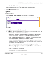
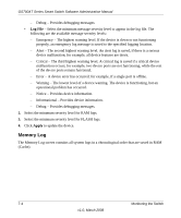
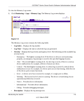
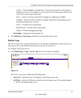
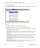
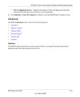
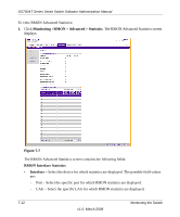
GS700AT Series Smart Switch Software Administration Manual - Critical - The third highest warning level. A critical log is saved if a critical device malfunction occurs; for example, two device ports are not functioning, while the rest of the device ports remain functional. - Error - A device error has occurred; for example, if a single port is offline. - Warning - The lowest level of a device warning. The device is functioning, but an operational problem has occurred. - Notice - Provides device information. - Informational - Provides device information. - Debug - Provides debugging messages. • Description - Displays the log message text. 2. Click Refresh or Clear Logs to refresh or reset the Flash Logs screen. Server Log The Server Log screen contains information for viewing and configuring the remote log servers. New log servers can be defined and the log severity sent to each server. To configure remote log servers: 1. Click Monitoring > Logs > Server Log. The Server Log screen displays: Figure 7-5 The Server Log screen contains the following fields: • Server IP - Enter the server's IP address to which logs can be sent. • UDP Port - Enter the UDP port to which the server logs are sent. The possible range is 1 - 65535. The default value is 514. Monitoring the Switch 7-7 v1.0, March 2008
-
 1
1 -
2
-
3
-
4
-
5
-
6
-
7
-
8
-
9
-
10
-
11
-
12
-
13
-
14
-
15
-
16
-
17
-
18
-
19
-
20
-
21
-
22
-
23
-
24
-
25
-
26
-
27
-
28
-
29
-
30
-
31
-
32
-
33
-
34
-
35
-
36
-
37
-
38
-
39
-
40
-
41
-
42
-
43
-
44
-
45
-
46
-
47
-
48
-
49
-
50
-
51
-
52
-
53
-
54
-
55
-
56
-
57
-
58
-
59
-
60
-
61
-
62
-
63
-
64
-
65
-
66
-
67
-
68
-
69
-
70
-
71
-
72
-
73
-
74
-
75
-
76
-
77
-
78
-
79
-
80
-
81
-
82
-
83
-
84
-
85
-
86
-
87
-
88
-
89
-
90
-
91
-
92
-
93
-
94
-
95
-
96
-
97
-
98
-
99
-
100
-
101
-
102
-
103
-
104
-
105
-
106
-
107
-
108
-
109
-
110
-
111
-
112
-
113
-
114
-
115
-
116
-
117
-
118
-
119
-
120
-
121
-
122
-
123
-
124
-
125
-
126
-
127
-
128
-
129
-
130
-
131
-
132
-
133
-
134
-
135
-
136
-
137
-
138
-
139
-
140
-
141
-
142
-
143
-
144
-
145
-
146
-
147
-
148
-
149
-
150
-
151
-
152
-
153
-
154
-
155
-
156
-
157
-
158
-
159
-
160
-
161
-
162
-
163
-
164
-
165
-
166
-
167
-
168
-
169
-
170
-
171
-
172
-
 173
173 -
 174
174 -
 175
175 -
 176
176 -
 177
177 -
 178
178 -
 179
179 -
 180
180 -
 181
181 -
 182
182 -
 183
183 -
184
-
185
-
186
-
187
-
188
-
189
-
190
-
191
-
192
-
193
-
194
-
195
-
196
-
197
-
198
-
199
-
200
-
201
-
202
-
203
-
204
-
205
-
206
-
207
-
208
-
209
 |
 |