Netgear GS724AT GS724AT Reference Manual - Page 39
Time, Dynamic IP Address DHCP
 |
UPC - 606449056907
View all Netgear GS724AT manuals
Add to My Manuals
Save this manual to your list of manuals |
Page 39 highlights
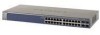
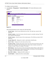
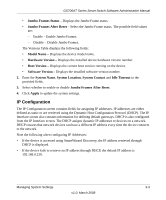
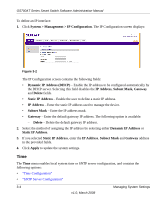
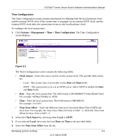
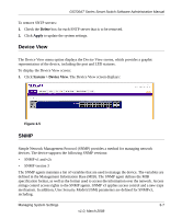
GS700AT Series Smart Switch Software Administration Manual To define an IP interface: 1. Click System > Management > IP Configuration. The IP Configuration screen displays: Figure 3-2 The IP Configuration screen contains the following fields: • Dynamic IP Address (DHCP) - Enable the IP address to be configured automatically by the DHCP server. Selecting this field disables the IP Address, Subnet Mask, Gateway and Delete fields. • Static IP Address - Enable the user to define a static IP address. • IP Address - Enter the static IP address used to manage the device. • Subnet Mask - Enter the IP address mask. • Gateway - Enter the default gateway IP address. The following option is available: - Delete - Delete the default gateway IP address. 2. Select the method of assigning the IP address by selecting either Dynamic IP Address or Static IP Address. 3. If you selected Static IP Address, enter the IP Address, Subnet Mask and Gateway address in the provided fields. 4. Click Apply to update the system settings. Time The Time menu enables local system time or SNTP server configuration, and contains the following options: • "Time Configuration" • "SNTP Server Configuration" 3-4 Managing System Settings v1.0, March 2008
-
 1
1 -
2
-
3
-
4
-
5
-
6
-
7
-
8
-
9
-
10
-
11
-
12
-
13
-
14
-
15
-
16
-
17
-
18
-
19
-
20
-
21
-
22
-
23
-
24
-
25
-
26
-
27
-
28
-
29
-
30
-
31
-
32
-
33
-
 34
34 -
 35
35 -
 36
36 -
 37
37 -
 38
38 -
 39
39 -
 40
40 -
 41
41 -
 42
42 -
 43
43 -
 44
44 -
45
-
46
-
47
-
48
-
49
-
50
-
51
-
52
-
53
-
54
-
55
-
56
-
57
-
58
-
59
-
60
-
61
-
62
-
63
-
64
-
65
-
66
-
67
-
68
-
69
-
70
-
71
-
72
-
73
-
74
-
75
-
76
-
77
-
78
-
79
-
80
-
81
-
82
-
83
-
84
-
85
-
86
-
87
-
88
-
89
-
90
-
91
-
92
-
93
-
94
-
95
-
96
-
97
-
98
-
99
-
100
-
101
-
102
-
103
-
104
-
105
-
106
-
107
-
108
-
109
-
110
-
111
-
112
-
113
-
114
-
115
-
116
-
117
-
118
-
119
-
120
-
121
-
122
-
123
-
124
-
125
-
126
-
127
-
128
-
129
-
130
-
131
-
132
-
133
-
134
-
135
-
136
-
137
-
138
-
139
-
140
-
141
-
142
-
143
-
144
-
145
-
146
-
147
-
148
-
149
-
150
-
151
-
152
-
153
-
154
-
155
-
156
-
157
-
158
-
159
-
160
-
161
-
162
-
163
-
164
-
165
-
166
-
167
-
168
-
169
-
170
-
171
-
172
-
173
-
174
-
175
-
176
-
177
-
178
-
179
-
180
-
181
-
182
-
183
-
184
-
185
-
186
-
187
-
188
-
189
-
190
-
191
-
192
-
193
-
194
-
195
-
196
-
197
-
198
-
199
-
200
-
201
-
202
-
203
-
204
-
205
-
206
-
207
-
208
-
209
 |
 |