Netgear GS724AT GS724AT Reference Manual - Page 85
LAG, MDIX Media Dependent Interface with Crossover - Connect HUBs and switches. - link aggregation
 |
UPC - 606449056907
View all Netgear GS724AT manuals
Add to My Manuals
Save this manual to your list of manuals |
Page 85 highlights
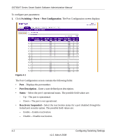
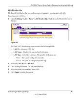
GS700AT Series Smart Switch Software Administration Manual • MDI/MDIX - Select the MDI/MDIX status of the port. Hubs and switches are deliberately wired opposite the way end stations are wired, so that when a hub or switch is connected to an end station, a straight through Ethernet cable can be used and the pairs will match up properly. When two hubs or switches are connected to each other or two end stations are connected to each other, a crossover cable is used to ensure that the correct pairs are connected. The possible field values are: - Auto - Provide automatic cable type detection. - MDI (Media Dependent Interface) - Connect end stations. - MDIX (Media Dependent Interface with Crossover) - Connect HUBs and switches. • LAG ID - Select the LAG ID to which the selected port is assigned. 2. Select the interface. 3. Enter or modify the fields in the first row. 4. Click Apply to update the device. LAG A Link Aggregated Group (LAG) optimizes port usage by linking a group of ports together to form a single LAG. Aggregating ports multiplies the bandwidth between the devices, increases port flexibility, and provides link redundancy. Ports added to a LAG lose their individual port configuration. When ports are removed from the LAG, the original port configuration is applied to the ports. Ensure the following, when configuring LAGs: • All ports within a LAG must be of the same media type. • A VLAN is not configured on the port. • The port is not assigned to a different LAG. • Auto-negotiation mode is not configured on the port. • The port is in full-duplex mode. • All ports in the LAG have the same ingress filtering and tagged modes. • All ports in the LAG have the same back pressure and flow control modes. • All ports in the LAG have the same priority. • All ports in the LAG have the same transceiver type. • The device supports up to eight LAGs with eight ports in each LAG. 4-4 Configuring Switching Settings v1.0, March 2008
-
 1
1 -
2
-
3
-
4
-
5
-
6
-
7
-
8
-
9
-
10
-
11
-
12
-
13
-
14
-
15
-
16
-
17
-
18
-
19
-
20
-
21
-
22
-
23
-
24
-
25
-
26
-
27
-
28
-
29
-
30
-
31
-
32
-
33
-
34
-
35
-
36
-
37
-
38
-
39
-
40
-
41
-
42
-
43
-
44
-
45
-
46
-
47
-
48
-
49
-
50
-
51
-
52
-
53
-
54
-
55
-
56
-
57
-
58
-
59
-
60
-
61
-
62
-
63
-
64
-
65
-
66
-
67
-
68
-
69
-
70
-
71
-
72
-
73
-
74
-
75
-
76
-
77
-
78
-
79
-
 80
80 -
 81
81 -
 82
82 -
 83
83 -
 84
84 -
 85
85 -
 86
86 -
 87
87 -
 88
88 -
 89
89 -
 90
90 -
91
-
92
-
93
-
94
-
95
-
96
-
97
-
98
-
99
-
100
-
101
-
102
-
103
-
104
-
105
-
106
-
107
-
108
-
109
-
110
-
111
-
112
-
113
-
114
-
115
-
116
-
117
-
118
-
119
-
120
-
121
-
122
-
123
-
124
-
125
-
126
-
127
-
128
-
129
-
130
-
131
-
132
-
133
-
134
-
135
-
136
-
137
-
138
-
139
-
140
-
141
-
142
-
143
-
144
-
145
-
146
-
147
-
148
-
149
-
150
-
151
-
152
-
153
-
154
-
155
-
156
-
157
-
158
-
159
-
160
-
161
-
162
-
163
-
164
-
165
-
166
-
167
-
168
-
169
-
170
-
171
-
172
-
173
-
174
-
175
-
176
-
177
-
178
-
179
-
180
-
181
-
182
-
183
-
184
-
185
-
186
-
187
-
188
-
189
-
190
-
191
-
192
-
193
-
194
-
195
-
196
-
197
-
198
-
199
-
200
-
201
-
202
-
203
-
204
-
205
-
206
-
207
-
208
-
209
 |
 |
