Netgear GS724AT GS724AT Reference Manual - Page 116
Interface, STP Status, Fast Link, Port State, Speed, Path Cost, Priority, can learn new MAC addresses.
 |
UPC - 606449056907
View all Netgear GS724AT manuals
Add to My Manuals
Save this manual to your list of manuals |
Page 116 highlights
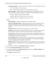
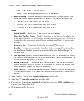
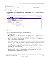
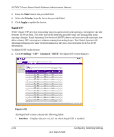
GS700AT Series Smart Switch Software Administration Manual The CST Port Configuration screen contains the following fields: • Interface - Displays the port or LAG for which the STP information is displayed. • STP Status - Select the STP status on the interface. The possible field values are: - Enable - Enable STP on the interface. - Disable - Disable STP on the interface. • Fast Link - Select the Fast Link state on the interface. If Fast Link mode is enabled for a interface, the Port State is automatically placed in the Forwarding state when the port link is up. Fast Link optimizes the STP protocol convergence. The possible field values are: - Enable - Enable Fast Link on the interface. - Disable - Disable Fast Link on the interface. • Port State - Displays the current STP state of a port. If enabled, the port state determines what forwarding action is taken on traffic. Possible port states are: - Forwarding - STP is enabled on the port, and the port is forwarding packets based on the STP topology. - Disabled - STP is currently disabled on the port. The port forwards traffic while learning MAC addresses. - Blocking - The port is currently blocked and cannot forward traffic or learn MAC addresses. - Listening - The port is in Listening mode. The port cannot forward traffic nor can it learn MAC addresses. - Learning - The port is in Learning mode. The port cannot forward traffic, however it can learn new MAC addresses. • Speed - Displays the speed at which the port is operating. • Path Cost - Enter the method used to assign default path cost to STP ports. The possible field range is 1 - 200000000. The default path cost assigned to an interface varies according to the selected CST configuration method (Hello Time, Max Age or Forward Delay). • Priority - Select the port priority value. When switches or ports are running STP, each is assigned a priority. After exchanging BPDUs, the device with the lowest priority value becomes the Root Port. The port priority has a range of 0-240 in increments of 16. The default value is 128. 2. Select the STP Status and Fast Link status in the provided fields. Configuring Switching Settings v1.0, March 2008 4-35
-
 1
1 -
2
-
3
-
4
-
5
-
6
-
7
-
8
-
9
-
10
-
11
-
12
-
13
-
14
-
15
-
16
-
17
-
18
-
19
-
20
-
21
-
22
-
23
-
24
-
25
-
26
-
27
-
28
-
29
-
30
-
31
-
32
-
33
-
34
-
35
-
36
-
37
-
38
-
39
-
40
-
41
-
42
-
43
-
44
-
45
-
46
-
47
-
48
-
49
-
50
-
51
-
52
-
53
-
54
-
55
-
56
-
57
-
58
-
59
-
60
-
61
-
62
-
63
-
64
-
65
-
66
-
67
-
68
-
69
-
70
-
71
-
72
-
73
-
74
-
75
-
76
-
77
-
78
-
79
-
80
-
81
-
82
-
83
-
84
-
85
-
86
-
87
-
88
-
89
-
90
-
91
-
92
-
93
-
94
-
95
-
96
-
97
-
98
-
99
-
100
-
101
-
102
-
103
-
104
-
105
-
106
-
107
-
108
-
109
-
110
-
 111
111 -
 112
112 -
 113
113 -
 114
114 -
 115
115 -
 116
116 -
 117
117 -
 118
118 -
 119
119 -
 120
120 -
 121
121 -
122
-
123
-
124
-
125
-
126
-
127
-
128
-
129
-
130
-
131
-
132
-
133
-
134
-
135
-
136
-
137
-
138
-
139
-
140
-
141
-
142
-
143
-
144
-
145
-
146
-
147
-
148
-
149
-
150
-
151
-
152
-
153
-
154
-
155
-
156
-
157
-
158
-
159
-
160
-
161
-
162
-
163
-
164
-
165
-
166
-
167
-
168
-
169
-
170
-
171
-
172
-
173
-
174
-
175
-
176
-
177
-
178
-
179
-
180
-
181
-
182
-
183
-
184
-
185
-
186
-
187
-
188
-
189
-
190
-
191
-
192
-
193
-
194
-
195
-
196
-
197
-
198
-
199
-
200
-
201
-
202
-
203
-
204
-
205
-
206
-
207
-
208
-
209
 |
 |