Netgear GS724AT GS724AT Reference Manual - Page 191
Alarms, The RMON Alarms screen displays
 |
UPC - 606449056907
View all Netgear GS724AT manuals
Add to My Manuals
Save this manual to your list of manuals |
Page 191 highlights
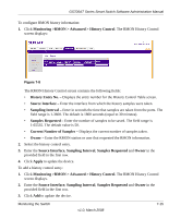
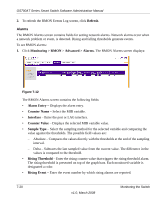
GS700AT Series Smart Switch Software Administration Manual 2. To refresh the RMON Events Log screen, click Refresh. Alarms The RMON Alarms screen contains fields for setting network alarms. Network alarms occur when a network problem or event, is detected. Rising and falling thresholds generate events. To set RMON alarms: 1. Click Monitoring > RMON > Advanced > Alarms. The RMON Alarms screen displays: Figure 7-12 The RMON Alarms screen contains the following fields: • Alarm Entry - Displays the alarm entry. • Counter Name - Select the MIB variable. • Interface - Enter the port or LAG interface. • Counter Value - Displays the selected MIB variable value. • Sample Type - Select the sampling method for the selected variable and comparing the value against the thresholds. The possible field values are: - Absolute - Compares the values directly with the thresholds at the end of the sampling interval. - Delta - Subtracts the last sampled value from the current value. The difference in the values is compared to the threshold. • Rising Threshold - Enter the rising counter value that triggers the rising threshold alarm. The rising threshold is presented on top of the graph bars. Each monitored variable is designated a color. • Rising Event - Enter the event number by which rising alarms are reported. 7-20 v1.0, March 2008 Monitoring the Switch
-
 1
1 -
2
-
3
-
4
-
5
-
6
-
7
-
8
-
9
-
10
-
11
-
12
-
13
-
14
-
15
-
16
-
17
-
18
-
19
-
20
-
21
-
22
-
23
-
24
-
25
-
26
-
27
-
28
-
29
-
30
-
31
-
32
-
33
-
34
-
35
-
36
-
37
-
38
-
39
-
40
-
41
-
42
-
43
-
44
-
45
-
46
-
47
-
48
-
49
-
50
-
51
-
52
-
53
-
54
-
55
-
56
-
57
-
58
-
59
-
60
-
61
-
62
-
63
-
64
-
65
-
66
-
67
-
68
-
69
-
70
-
71
-
72
-
73
-
74
-
75
-
76
-
77
-
78
-
79
-
80
-
81
-
82
-
83
-
84
-
85
-
86
-
87
-
88
-
89
-
90
-
91
-
92
-
93
-
94
-
95
-
96
-
97
-
98
-
99
-
100
-
101
-
102
-
103
-
104
-
105
-
106
-
107
-
108
-
109
-
110
-
111
-
112
-
113
-
114
-
115
-
116
-
117
-
118
-
119
-
120
-
121
-
122
-
123
-
124
-
125
-
126
-
127
-
128
-
129
-
130
-
131
-
132
-
133
-
134
-
135
-
136
-
137
-
138
-
139
-
140
-
141
-
142
-
143
-
144
-
145
-
146
-
147
-
148
-
149
-
150
-
151
-
152
-
153
-
154
-
155
-
156
-
157
-
158
-
159
-
160
-
161
-
162
-
163
-
164
-
165
-
166
-
167
-
168
-
169
-
170
-
171
-
172
-
173
-
174
-
175
-
176
-
177
-
178
-
179
-
180
-
181
-
182
-
183
-
184
-
185
-
 186
186 -
 187
187 -
 188
188 -
 189
189 -
 190
190 -
 191
191 -
 192
192 -
 193
193 -
 194
194 -
 195
195 -
 196
196 -
197
-
198
-
199
-
200
-
201
-
202
-
203
-
204
-
205
-
206
-
207
-
208
-
209
 |
 |