Nintendo 1504166 Programming Manual - Page 113
DMA 1 and 2, Thus, in 16-bit data transfer mode, up to 4000h x 2=8000h bytes can
 |
View all Nintendo 1504166 manuals
Add to My Manuals
Save this manual to your list of manuals |
Page 113 highlights
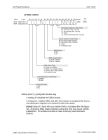
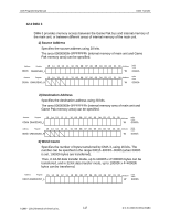
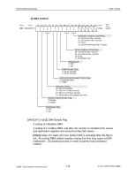
AGB Programming Manual DMA Transfer 12.2 DMA 1 and 2 DMA channels 1 and 2 provide access between the Game Pak bus/internal memory of the main unit and internal memory of the main unit, or between the Game Pak bus/internal memory of the main unit and the direct sound FIFO. Transfers to directsound FIFO can be accomplished only by using DMA 1 and 2. 1) Source Address Specifies the source address using 28 bits. The area 00000000h-0FFFFFFFh can be specified. Address Register 15 14 13 12 11 10 09 08 07 06 05 04 03 02 01 00 Attributes 0BCh DMA1SAD_L 0C8h DMA2SAD_L W Initial Value 0000h Address Register 15 14 13 12 11 10 09 08 07 06 05 04 03 02 01 00 Attributes Initial Value 0BEh DMA1SAD_H 0CAh DMA2SAD_H W 0000h 2) Destination Address Specifies the destination address using 27 bits. The area 00000000h-07FFFFFFh (internal memory area of main unit) can be specified. Address Register 15 14 13 12 11 10 09 08 07 06 05 04 03 02 01 00 Attributes Initial Value 0C0h DMA1DAD_L 0CCh DMA2DAD_L W 0000h Address Register 15 14 13 12 11 10 09 08 07 06 05 04 03 02 01 00 Attributes Initial Value 0C2h DMA1DAD_H W 0000h 0CEh DMA2DAD_H 3) Word Count Specifies the number of bytes transferred by DMA 1 and DMA 2, using 14 bits. The number can be specified in the range 0001h~3FFFh~0000h (when 0000h is set, 4000h bytes are transferred). Thus, in 16-bit data transfer mode, up to 4000h x 2=8000h bytes can be transferred, and in 32-bit data transfer mode, up to 4000h x 4=10000h bytes can be transferred. Address Register 15 14 13 12 11 10 09 08 07 06 05 04 03 02 01 00 Attributes Initial Value 0C4h DMA1CNT_L 0D0h DMA2CNT_L W 0000h The word-count register setting is disabled in direct-sound FIFO transfer mode. With each request received from sound FIFO, 32 bits x 4 words of sound data are transferred. ©1999 - 2001 Nintendo of America Inc. 113 D.C.N. AGB-06-0001-002B4
-
 1
1 -
2
-
3
-
4
-
5
-
6
-
7
-
8
-
9
-
10
-
11
-
12
-
13
-
14
-
15
-
16
-
17
-
18
-
19
-
20
-
21
-
22
-
23
-
24
-
25
-
26
-
27
-
28
-
29
-
30
-
31
-
32
-
33
-
34
-
35
-
36
-
37
-
38
-
39
-
40
-
41
-
42
-
43
-
44
-
45
-
46
-
47
-
48
-
49
-
50
-
51
-
52
-
53
-
54
-
55
-
56
-
57
-
58
-
59
-
60
-
61
-
62
-
63
-
64
-
65
-
66
-
67
-
68
-
69
-
70
-
71
-
72
-
73
-
74
-
75
-
76
-
77
-
78
-
79
-
80
-
81
-
82
-
83
-
84
-
85
-
86
-
87
-
88
-
89
-
90
-
91
-
92
-
93
-
94
-
95
-
96
-
97
-
98
-
99
-
100
-
101
-
102
-
103
-
104
-
105
-
106
-
107
-
 108
108 -
 109
109 -
 110
110 -
 111
111 -
 112
112 -
 113
113 -
 114
114 -
 115
115 -
 116
116 -
 117
117 -
 118
118 -
119
-
120
-
121
-
122
-
123
-
124
-
125
-
126
-
127
-
128
-
129
-
130
-
131
-
132
-
133
-
134
-
135
-
136
-
137
-
138
-
139
-
140
-
141
-
142
-
143
-
144
-
145
-
146
-
147
-
148
-
149
-
150
-
151
-
152
-
153
-
154
-
155
-
156
-
157
-
158
-
159
-
160
-
161
-
162
-
163
-
164
-
165
-
166
-
167
-
168
-
169
-
170
-
171
 |
 |
