Nintendo 1504166 Programming Manual - Page 85
Direct Sounds A and B, Using sound control register SOUNDCNT_H, do a 0 clear with FIFO A and FIFO
 |
View all Nintendo 1504166 manuals
Add to My Manuals
Save this manual to your list of manuals |
Page 85 highlights
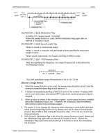
AGB Programming Manual Sound 10.2 Direct Sounds A and B Direct sounds have 2 channels, A and B. Linear 8-bit audio data can be played back. The audio data are set to a bias level of 00h and are 8-bit data (+127 to -128), obtained by 2's complement. Audio data are transferred sequentially to the sound FIFO (8-word capacity), using the sound FIFO transfer mode of DMA 1 and 2. The sampling rate can be set to an arbitrary value using timers 0 and 1. Sound FIFO Input Register Address 0A0h 0A4h Register FIFO_A_L FIFO_B_L 15 14 13 12 11 10 09 08 07 06 05 04 03 02 01 00 Attributes Initial Value Sound Data 1 Sound Data 0 W - Address 0A2h 0A6h Register FIFO_A_H FIFO_B_H 15 14 13 12 11 10 Sound Data 3 09 08 07 06 05 04 03 02 Sound Data 2 01 00 Attributes Initial Value W - Sound Data All sounds are PWM modulated (refer to 10.8 "Sound PWM Control") at the final portion of the Sound Circuit. Therefore, if you match the 8 bit audio data sampling frequency and the timer settings with the PWM modulation sampling frequency, a clean sound can be produced. The following operations are repeated for direct sound. Preparing to Use Direct Sound 1. Using sound control register SOUNDCNT_H (refer to 10.7 "Sound Control"), select the timer channel to be used (0 or 1). 2. Using sound control register SOUNDCNT_H, do a 0 clear with FIFO A and FIFO B, and initialize the sequencer. 3. In cases of producing a sound immediately after starting the direct sound, write the first 8 bits of linear audio data to the FIFO with a CPU write. 4. Specify the transfer mode for DMA 1 or 2 (see 12.2 "DMA 1 and 2"). 5. Specify the direct sound outputs settings in the sound control register. 6. Start the timer. ©1999 - 2001 Nintendo of America Inc. 85 D.C.N. AGB-06-0001-002B4
-
 1
1 -
2
-
3
-
4
-
5
-
6
-
7
-
8
-
9
-
10
-
11
-
12
-
13
-
14
-
15
-
16
-
17
-
18
-
19
-
20
-
21
-
22
-
23
-
24
-
25
-
26
-
27
-
28
-
29
-
30
-
31
-
32
-
33
-
34
-
35
-
36
-
37
-
38
-
39
-
40
-
41
-
42
-
43
-
44
-
45
-
46
-
47
-
48
-
49
-
50
-
51
-
52
-
53
-
54
-
55
-
56
-
57
-
58
-
59
-
60
-
61
-
62
-
63
-
64
-
65
-
66
-
67
-
68
-
69
-
70
-
71
-
72
-
73
-
74
-
75
-
76
-
77
-
78
-
79
-
 80
80 -
 81
81 -
 82
82 -
 83
83 -
 84
84 -
 85
85 -
 86
86 -
 87
87 -
 88
88 -
 89
89 -
 90
90 -
91
-
92
-
93
-
94
-
95
-
96
-
97
-
98
-
99
-
100
-
101
-
102
-
103
-
104
-
105
-
106
-
107
-
108
-
109
-
110
-
111
-
112
-
113
-
114
-
115
-
116
-
117
-
118
-
119
-
120
-
121
-
122
-
123
-
124
-
125
-
126
-
127
-
128
-
129
-
130
-
131
-
132
-
133
-
134
-
135
-
136
-
137
-
138
-
139
-
140
-
141
-
142
-
143
-
144
-
145
-
146
-
147
-
148
-
149
-
150
-
151
-
152
-
153
-
154
-
155
-
156
-
157
-
158
-
159
-
160
-
161
-
162
-
163
-
164
-
165
-
166
-
167
-
168
-
169
-
170
-
171
 |
 |
