Nintendo 1504166 Programming Manual - Page 30
OBJ Character VRAM Mapping Format, H-Blank Interval OBJ Processing Flag
 |
View all Nintendo 1504166 manuals
Add to My Manuals
Save this manual to your list of manuals |
Page 30 highlights
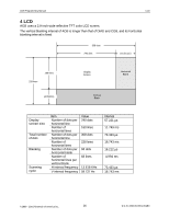
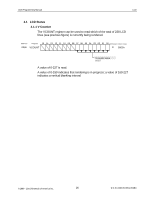
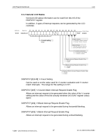
AGB Programming Manual Image System DISPCNT [d07] Forced Blank Setting this bit causes the CPU to forcibly halt operation of the image processing circuit, allowing access to VRAM, color palette RAM, OAM, and the internal registers. The LCD screen displays white during a forced blank. However, the internal HV synchronous counter continues to operate even during a forced blank. When the internal HV synchronous counter cancels a forced blank during a display period, the display begins from the beginning, following the display of three vertical lines. DISPCNT [d06] OBJ Character VRAM Mapping Format Specifies the VRAM mapping format for an OBJ character. A setting of 0 causes the OBJ character to be handled in memory mapped 2-dimensional. A setting of 1 causes the OBJ character to be handled in memory mapped 1-dimensional. For information on OBJ character VRAM mapping formats, see section 6.3.2, Character Data Mapping. DISPCNT [d05] H-Blank Interval OBJ Processing Flag A setting of 0 executes OBJ Render Processing with all H-Line intervals(including H-Blank intervals). A setting of 1 executes OBJ Render Processing with the display intervals only and not for H-Blank intervals. Thus, when the user accesses OAM or OBJ VRAM during an H-Blank interval, this bit needs to be set. However, also in this situation, maximum OBJ display performance cannot be obtained. DISPCNT [d04] Display Frame Selection When rendering in bitmap format in a mode in which there are 2 frame buffers (BG modes 4 and 5), this bit allows selection of one of the frame buffers for rendering. A setting of 0 selects the contents of frame buffer 0 for rendering; a setting of 1 selects the contents of frame buffer 1 for rendering. DISPCNT [d03] (CGB Mode) AGB is equipped with 2 CPUs. In AGB mode, a 32-bit RISC CPU starts, and in CGB mode, an 8-bit CISC CPU starts. Because this bit is controlled by the system, it cannot be accessed by the user. DISPCNT [d02-00] BG Mode Selects the BG mode from a range of 0-5. For more information on BG modes, see the following section. ©1999 - 2001 Nintendo of America Inc. 30 D.C.N. AGB-06-0001-002B4
-
 1
1 -
2
-
3
-
4
-
5
-
6
-
7
-
8
-
9
-
10
-
11
-
12
-
13
-
14
-
15
-
16
-
17
-
18
-
19
-
20
-
21
-
22
-
23
-
24
-
 25
25 -
 26
26 -
 27
27 -
 28
28 -
 29
29 -
 30
30 -
 31
31 -
 32
32 -
 33
33 -
 34
34 -
 35
35 -
36
-
37
-
38
-
39
-
40
-
41
-
42
-
43
-
44
-
45
-
46
-
47
-
48
-
49
-
50
-
51
-
52
-
53
-
54
-
55
-
56
-
57
-
58
-
59
-
60
-
61
-
62
-
63
-
64
-
65
-
66
-
67
-
68
-
69
-
70
-
71
-
72
-
73
-
74
-
75
-
76
-
77
-
78
-
79
-
80
-
81
-
82
-
83
-
84
-
85
-
86
-
87
-
88
-
89
-
90
-
91
-
92
-
93
-
94
-
95
-
96
-
97
-
98
-
99
-
100
-
101
-
102
-
103
-
104
-
105
-
106
-
107
-
108
-
109
-
110
-
111
-
112
-
113
-
114
-
115
-
116
-
117
-
118
-
119
-
120
-
121
-
122
-
123
-
124
-
125
-
126
-
127
-
128
-
129
-
130
-
131
-
132
-
133
-
134
-
135
-
136
-
137
-
138
-
139
-
140
-
141
-
142
-
143
-
144
-
145
-
146
-
147
-
148
-
149
-
150
-
151
-
152
-
153
-
154
-
155
-
156
-
157
-
158
-
159
-
160
-
161
-
162
-
163
-
164
-
165
-
166
-
167
-
168
-
169
-
170
-
171
 |
 |
