Dell Latitude 7030 Rugged Extreme Tablet Owners Manual - Page 115
Removing the system board, World-facing camera FPC
 |
View all Dell Latitude 7030 Rugged Extreme Tablet manuals
Add to My Manuals
Save this manual to your list of manuals |
Page 115 highlights
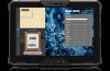
Figure 100. Removing the system board Steps 1. Loosen the two captive screws that secure the WWAN/SSD connector bracket to the system board. NOTE: Loosen the two captive screws in the reverse sequential order mentioned on the WWAN/SSD connector bracket [2 > 1]. 2. Lift the WWAN/SSD connector bracket off the system board. 3. Disconnect and remove the WWAN FPC from the connector on the system board and the WWAN/SSD daughter-board. 4. Disconnect and remove the SSD FPC from the connector on the system board and the WWAN/SSD daughter-board. 5. Remove the three screws (M2x3) that secure the camera-connector bracket to the system board. NOTE: Steps 5 and 6 apply only to tablets shipped with a front-facing camera and microphone assembly or microphone assembly. 6. Lift the camera-connector bracket off the system board. 7. For tablets shipped with WLAN antennas only, disconnect the red GPS antenna cable, white WLAN Aux P-sensor cable, and red WLAN Main P-sensor cable from the connectors on the system board. 8. For tablets shipped with WWAN antennas, disconnect the red GPS antenna cable, white WLAN Aux P-sensor cable, black MIMO 2 P-sensor cable, red WLAN Main P-sensor cable, and green WWAN main cable from the connectors on the system board. 9. Loosen the two captive screws that secure the docking FPC bracket to the system board. 10. Remove the docking FPC bracket from the system board. 11. Disconnect the following cables from the system board: a. World-facing camera FPC NOTE: This step applies only to tablets shipped with a world-facing camera installed. b. Front-camera and microphone assembly FPC Removing and installing Field Replaceable Units (FRUs) 115
-
 1
1 -
2
-
3
-
4
-
5
-
6
-
7
-
8
-
9
-
10
-
11
-
12
-
13
-
14
-
15
-
16
-
17
-
18
-
19
-
20
-
21
-
22
-
23
-
24
-
25
-
26
-
27
-
28
-
29
-
30
-
31
-
32
-
33
-
34
-
35
-
36
-
37
-
38
-
39
-
40
-
41
-
42
-
43
-
44
-
45
-
46
-
47
-
48
-
49
-
50
-
51
-
52
-
53
-
54
-
55
-
56
-
57
-
58
-
59
-
60
-
61
-
62
-
63
-
64
-
65
-
66
-
67
-
68
-
69
-
70
-
71
-
72
-
73
-
74
-
75
-
76
-
77
-
78
-
79
-
80
-
81
-
82
-
83
-
84
-
85
-
86
-
87
-
88
-
89
-
90
-
91
-
92
-
93
-
94
-
95
-
96
-
97
-
98
-
99
-
100
-
101
-
102
-
103
-
104
-
105
-
106
-
107
-
108
-
109
-
 110
110 -
 111
111 -
 112
112 -
 113
113 -
 114
114 -
 115
115 -
 116
116 -
 117
117 -
 118
118 -
 119
119 -
 120
120 -
121
-
122
-
123
-
124
-
125
-
126
-
127
-
128
-
129
-
130
-
131
-
132
-
133
-
134
-
135
-
136
-
137
-
138
-
139
-
140
-
141
-
142
-
143
-
144
-
145
-
146
-
147
-
148
-
149
-
150
-
151
-
152
-
153
-
154
-
155
-
156
-
157
 |
 |
