Dell Latitude 7030 Rugged Extreme Tablet Owners Manual - Page 116
Installing the system board, Removing the system board
 |
View all Dell Latitude 7030 Rugged Extreme Tablet manuals
Add to My Manuals
Save this manual to your list of manuals |
Page 116 highlights
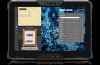
NOTE: This step applies only to tablets shipped with a front camera and microphone assembly or microphone assembly installed. c. Touch-screen FPC d. Display cable e. Function-button FPC f. Docking FPC g. Speaker cable 12. Loosen the captive screw that secures the USB Type-C bracket to the display assembly. 13. Remove the three screws (M2x3) that secure the system board to the display assembly. 14. Remove the system board, along with the coin-cell battery, from the display assembly. NOTE: The system board includes a USB Type-C bracket which must not be removed. Figure 101. Removing the system board Installing the system board CAUTION: The information in this installation section is intended for authorized service technicians only. Prerequisites If you are replacing a component, remove the existing component before performing the installation procedure. About this task The following image indicates the connectors on your system board. 116 Removing and installing Field Replaceable Units (FRUs)
-
 1
1 -
2
-
3
-
4
-
5
-
6
-
7
-
8
-
9
-
10
-
11
-
12
-
13
-
14
-
15
-
16
-
17
-
18
-
19
-
20
-
21
-
22
-
23
-
24
-
25
-
26
-
27
-
28
-
29
-
30
-
31
-
32
-
33
-
34
-
35
-
36
-
37
-
38
-
39
-
40
-
41
-
42
-
43
-
44
-
45
-
46
-
47
-
48
-
49
-
50
-
51
-
52
-
53
-
54
-
55
-
56
-
57
-
58
-
59
-
60
-
61
-
62
-
63
-
64
-
65
-
66
-
67
-
68
-
69
-
70
-
71
-
72
-
73
-
74
-
75
-
76
-
77
-
78
-
79
-
80
-
81
-
82
-
83
-
84
-
85
-
86
-
87
-
88
-
89
-
90
-
91
-
92
-
93
-
94
-
95
-
96
-
97
-
98
-
99
-
100
-
101
-
102
-
103
-
104
-
105
-
106
-
107
-
108
-
109
-
110
-
 111
111 -
 112
112 -
 113
113 -
 114
114 -
 115
115 -
 116
116 -
 117
117 -
 118
118 -
 119
119 -
 120
120 -
 121
121 -
122
-
123
-
124
-
125
-
126
-
127
-
128
-
129
-
130
-
131
-
132
-
133
-
134
-
135
-
136
-
137
-
138
-
139
-
140
-
141
-
142
-
143
-
144
-
145
-
146
-
147
-
148
-
149
-
150
-
151
-
152
-
153
-
154
-
155
-
156
-
157
 |
 |
