Dell Latitude 7030 Rugged Extreme Tablet Owners Manual - Page 120
Installing the system board
 |
View all Dell Latitude 7030 Rugged Extreme Tablet manuals
Add to My Manuals
Save this manual to your list of manuals |
Page 120 highlights
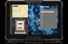
Figure 105. Installing the system board Steps 1. Align the screw holes on the system board with the screw holes on the display assembly. 2. Replace the three screws (M2x3) to secure the system board to the display assembly. 3. Tighten the captive screw to secure the USB Type-C bracket to the display assembly. 4. Connect the following cables to the connectors on the system board: a. World-facing camera FPC NOTE: This step applies only to tablets shipped with a world-facing camera installed. b. Front-camera and microphone assembly FPC NOTE: This step applies only to tablets shipped with a front camera and microphone assembly or microphone assembly installed. c. Touch-screen FPC d. Display cable e. Function-button FPC f. Docking FPC g. Speaker cable 5. Align the screw holes on the docking FPC bracket with the screw holes on the system board. 6. Tighten the two captive screws to secure the docking FPC bracket to the system board. 7. For tablets shipped with WWAN antennas, connect the red GPS antenna cable, white WLAN Aux P-sensor cable, black MIMO 2 P-sensor cable, red WLAN Main P-sensor cable, and green WWAN main cable to the connectors on the system board. 8. For tablets shipped with WLAN antennas only, connect the red GPS antenna cable, white WLAN Aux P-sensor cable, and red WLAN Main P-sensor cable to the connectors on the system board. 9. Align and place the camera-connector bracket on the system board. 10. Replace the three screws (M2x3) to secure the camera-connector bracket to the system board. 120 Removing and installing Field Replaceable Units (FRUs)
-
 1
1 -
2
-
3
-
4
-
5
-
6
-
7
-
8
-
9
-
10
-
11
-
12
-
13
-
14
-
15
-
16
-
17
-
18
-
19
-
20
-
21
-
22
-
23
-
24
-
25
-
26
-
27
-
28
-
29
-
30
-
31
-
32
-
33
-
34
-
35
-
36
-
37
-
38
-
39
-
40
-
41
-
42
-
43
-
44
-
45
-
46
-
47
-
48
-
49
-
50
-
51
-
52
-
53
-
54
-
55
-
56
-
57
-
58
-
59
-
60
-
61
-
62
-
63
-
64
-
65
-
66
-
67
-
68
-
69
-
70
-
71
-
72
-
73
-
74
-
75
-
76
-
77
-
78
-
79
-
80
-
81
-
82
-
83
-
84
-
85
-
86
-
87
-
88
-
89
-
90
-
91
-
92
-
93
-
94
-
95
-
96
-
97
-
98
-
99
-
100
-
101
-
102
-
103
-
104
-
105
-
106
-
107
-
108
-
109
-
110
-
111
-
112
-
113
-
114
-
 115
115 -
 116
116 -
 117
117 -
 118
118 -
 119
119 -
 120
120 -
 121
121 -
 122
122 -
 123
123 -
 124
124 -
 125
125 -
126
-
127
-
128
-
129
-
130
-
131
-
132
-
133
-
134
-
135
-
136
-
137
-
138
-
139
-
140
-
141
-
142
-
143
-
144
-
145
-
146
-
147
-
148
-
149
-
150
-
151
-
152
-
153
-
154
-
155
-
156
-
157
 |
 |
