Dell Latitude 7030 Rugged Extreme Tablet Owners Manual - Page 71
Installing the I/O daughter-board
 |
View all Dell Latitude 7030 Rugged Extreme Tablet manuals
Add to My Manuals
Save this manual to your list of manuals |
Page 71 highlights
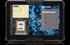
Figure 60. Installing the I/O daughter-board Steps 1. Align the screw holes on the I/O daughter-board with the screw holes on the display assembly. 2. Replace the screw (M2x6) to secure the I/O daughter-board to the display assembly. 3. Align the screw holes on the USB Type-C bracket to the system board. 4. Replace the three screws (M2x6) to secure the USB Type-C bracket to the system board. 5. Connect the I/O daughter-board FPC to the connector on the system board. 6. Align and place the I/O daughter-board FPC bracket on the FPC connector. 7. Tighten the two captive screws to secure the I/O daughter-board FPC bracket to the system board. Next steps 1. Install the back-cover assembly. 2. Install the hot-swappable batteries, if applicable. 3. Install the handle, if applicable. 4. Install the stylus. 5. Follow the procedure in After working inside your tablet. Removing and installing Field Replaceable Units (FRUs) 71
-
 1
1 -
2
-
3
-
4
-
5
-
6
-
7
-
8
-
9
-
10
-
11
-
12
-
13
-
14
-
15
-
16
-
17
-
18
-
19
-
20
-
21
-
22
-
23
-
24
-
25
-
26
-
27
-
28
-
29
-
30
-
31
-
32
-
33
-
34
-
35
-
36
-
37
-
38
-
39
-
40
-
41
-
42
-
43
-
44
-
45
-
46
-
47
-
48
-
49
-
50
-
51
-
52
-
53
-
54
-
55
-
56
-
57
-
58
-
59
-
60
-
61
-
62
-
63
-
64
-
65
-
 66
66 -
 67
67 -
 68
68 -
 69
69 -
 70
70 -
 71
71 -
 72
72 -
 73
73 -
 74
74 -
 75
75 -
 76
76 -
77
-
78
-
79
-
80
-
81
-
82
-
83
-
84
-
85
-
86
-
87
-
88
-
89
-
90
-
91
-
92
-
93
-
94
-
95
-
96
-
97
-
98
-
99
-
100
-
101
-
102
-
103
-
104
-
105
-
106
-
107
-
108
-
109
-
110
-
111
-
112
-
113
-
114
-
115
-
116
-
117
-
118
-
119
-
120
-
121
-
122
-
123
-
124
-
125
-
126
-
127
-
128
-
129
-
130
-
131
-
132
-
133
-
134
-
135
-
136
-
137
-
138
-
139
-
140
-
141
-
142
-
143
-
144
-
145
-
146
-
147
-
148
-
149
-
150
-
151
-
152
-
153
-
154
-
155
-
156
-
157
 |
 |
