Dell Latitude 7030 Rugged Extreme Tablet Owners Manual - Page 81
RJ45-port assembly, Removing the RJ45-port assembly
 |
View all Dell Latitude 7030 Rugged Extreme Tablet manuals
Add to My Manuals
Save this manual to your list of manuals |
Page 81 highlights
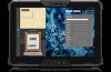
Prerequisites If you are replacing a component, remove the existing component before performing the installation procedure. About this task The following images indicate the location of the blank top-cover and provide a visual representation of the installation procedure. Figure 69. Installing the blank top-cover Steps 1. Align the screw holes on the blank top-cover with the screw holes on the display assembly. 2. Replace the four screws (M2x6) to secure the blank top-cover to the display assembly. Next steps 1. Install the back-cover assembly. 2. Install the hot-swappable batteries, if applicable. 3. Install the handle, if applicable. 4. Install the stylus. 5. Follow the procedure in After working inside your tablet. RJ45-port assembly Removing the RJ45-port assembly CAUTION: The information in this removal section is intended for authorized service technicians only. NOTE: This procedure applies only to tablets shipped with an RJ45 connector installed in the expansion bay at the top side of the tablet. Prerequisites 1. Follow the procedure in Before working inside your tablet. Removing and installing Field Replaceable Units (FRUs) 81
-
 1
1 -
2
-
3
-
4
-
5
-
6
-
7
-
8
-
9
-
10
-
11
-
12
-
13
-
14
-
15
-
16
-
17
-
18
-
19
-
20
-
21
-
22
-
23
-
24
-
25
-
26
-
27
-
28
-
29
-
30
-
31
-
32
-
33
-
34
-
35
-
36
-
37
-
38
-
39
-
40
-
41
-
42
-
43
-
44
-
45
-
46
-
47
-
48
-
49
-
50
-
51
-
52
-
53
-
54
-
55
-
56
-
57
-
58
-
59
-
60
-
61
-
62
-
63
-
64
-
65
-
66
-
67
-
68
-
69
-
70
-
71
-
72
-
73
-
74
-
75
-
 76
76 -
 77
77 -
 78
78 -
 79
79 -
 80
80 -
 81
81 -
 82
82 -
 83
83 -
 84
84 -
 85
85 -
 86
86 -
87
-
88
-
89
-
90
-
91
-
92
-
93
-
94
-
95
-
96
-
97
-
98
-
99
-
100
-
101
-
102
-
103
-
104
-
105
-
106
-
107
-
108
-
109
-
110
-
111
-
112
-
113
-
114
-
115
-
116
-
117
-
118
-
119
-
120
-
121
-
122
-
123
-
124
-
125
-
126
-
127
-
128
-
129
-
130
-
131
-
132
-
133
-
134
-
135
-
136
-
137
-
138
-
139
-
140
-
141
-
142
-
143
-
144
-
145
-
146
-
147
-
148
-
149
-
150
-
151
-
152
-
153
-
154
-
155
-
156
-
157
 |
 |
