Dell PowerConnect 2848 User's Guide - Page 24
Cables, Port Connections, and Pinout Information, 1000BASE-T Cable Requirements - specifications
 |
View all Dell PowerConnect 2848 manuals
Add to My Manuals
Save this manual to your list of manuals |
Page 24 highlights
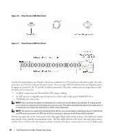
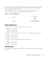
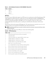
Cables, Port Connections, and Pinout Information This section explains the switch physical interfaces, and provides information about cables and port connections. Copper cable diagnostics are supported. High-speed workstations, hubs, routers, or other switches are connected through standard RJ-45 connectors to the switch physical interface ports, located on the front panel. For each device, the supported mode is set to Half Duplex, Full Duplex, and Auto. 1000BASE-T Cable Requirements All Category 5 UTP cables that are used for 100BASE-TX connections also operate with 1000BASE-T, provided if all four wire pairs are connected. However, it is recommended that enhanced Category 5 (Category 5e)cable is used for all critical connections or any new cable installations. The Category 5e specification includes test parameters that are only recommendations for Category 5, and comply with the IEEE 802.3ab standards. RJ-45 Connections for 10/100/1000BASE-T Ports The 10/100/1000BASE-T ports are copper Twisted-Pair ports. Table 2-6. Port Default Settings Connector RJ-45 Port/Interface 10/100/1000BASE-T Port Cable Cat.5 The following figure illustrates the RJ-45 pin connector pin numbers. Figure 2-10. RJ-45 Pin Numbers The RJ-45 pin number allocation for the 10/100/1000BASE-T ports is listed in the following table. Table 2-7. RJ-45 Pin Number Allocation for 10/100/ 1000BASE-T Ethernet Port Pin No 1 2 3 4 5 Function TxRx 1+ TxRx 1TxRx 2+ TxRx 2TxRx 3+ 24 Dell PowerConnect 28xx Systems User Guide
-
 1
1 -
2
-
3
-
4
-
5
-
6
-
7
-
8
-
9
-
10
-
11
-
12
-
13
-
14
-
15
-
16
-
17
-
18
-
 19
19 -
 20
20 -
 21
21 -
 22
22 -
 23
23 -
 24
24 -
 25
25 -
 26
26 -
 27
27 -
 28
28 -
 29
29 -
30
-
31
-
32
-
33
-
34
-
35
-
36
-
37
-
38
-
39
-
40
-
41
-
42
-
43
-
44
-
45
-
46
-
47
-
48
-
49
-
50
-
51
-
52
-
53
-
54
-
55
-
56
-
57
-
58
-
59
-
60
-
61
-
62
-
63
-
64
-
65
-
66
-
67
-
68
-
69
-
70
-
71
-
72
-
73
-
74
-
75
-
76
-
77
-
78
-
79
-
80
-
81
-
82
-
83
-
84
-
85
-
86
-
87
-
88
-
89
-
90
-
91
-
92
-
93
-
94
-
95
-
96
-
97
-
98
-
99
-
100
-
101
-
102
-
103
-
104
-
105
-
106
-
107
-
108
-
109
-
110
-
111
-
112
-
113
-
114
-
115
-
116
-
117
-
118
-
119
-
120
-
121
-
122
-
123
-
124
-
125
-
126
-
127
-
128
-
129
-
130
-
131
-
132
-
133
-
134
-
135
-
136
-
137
-
138
-
139
-
140
-
141
-
142
-
143
-
144
-
145
-
146
-
147
-
148
-
149
-
150
-
151
-
152
-
153
-
154
-
155
-
156
-
157
-
158
-
159
-
160
-
161
-
162
-
163
-
164
-
165
-
166
-
167
-
168
-
169
-
170
-
171
-
172
-
173
-
174
-
175
-
176
-
177
-
178
-
179
-
180
-
181
-
182
-
183
-
184
-
185
-
186
 |
 |