Dell PowerVault NX3500 Hardware Owner's Manual
Dell PowerVault NX3500 Manual
 |
View all Dell PowerVault NX3500 manuals
Add to My Manuals
Save this manual to your list of manuals |
Dell PowerVault NX3500 manual content summary:
- Dell PowerVault NX3500 | Hardware Owner's Manual - Page 1
Dell PowerVault NX3500 Systems Hardware Owner's Manual Regulatory Model: E07S Series, DELL500WLV, and DELL500WHV Regulatory Type: E07S002 - Dell PowerVault NX3500 | Hardware Owner's Manual - Page 2
A CAUTION indicates potential damage to hardware or loss of data if instructions are not followed. WARNING: A WARNING indicates a potential for property Dell Inc. and Eaton Corporation is strictly forbidden. Trademarks used in this text: Dell™, the DELL logo, and PowerVault™ are trademarks of Dell - Dell PowerVault NX3500 | Hardware Owner's Manual - Page 3
16 PowerVault NX3500 Back-Panel Features and Indicators 17 NIC Indicator Codes 18 Power Indicator Codes 19 Dell Backup Power Supply Front-Panel Features . . . 20 Backup Power Supply Indicators 21 Backup Power Supply Back-Panel Features 22 LCD Status Messages 22 Solving Problems Described - Dell PowerVault NX3500 | Hardware Owner's Manual - Page 4
48 Alert Messages 48 Other Information You May Need 48 2 Installing System Components 49 Recommended Tools 49 Inside the System 49 Front Bezel 51 Opening and Closing the System 52 Opening the System 52 Closing the System 53 Optical Drive 54 Removing an Optical Drive 54 Installing an - Dell PowerVault NX3500 | Hardware Owner's Manual - Page 5
Installing the Cooling Shroud 63 Integrated Storage Controller Card 64 Removing the Integrated Storage Controller Card 64 Installing the Integrated Storage Controller Card 66 System Memory 66 General Memory Module Installation Guidelines 67 Replacing Memory Modules 67 Cooling Fans 69 - Dell PowerVault NX3500 | Hardware Owner's Manual - Page 6
Your System 93 Troubleshooting System Startup Failure 93 Troubleshooting External Connections 93 Troubleshooting a NIC 93 Troubleshooting a Damaged System 94 Troubleshooting the System Battery 95 Troubleshooting Power Supply 96 Troubleshooting System Cooling Problems 96 Troubleshooting a Fan - Dell PowerVault NX3500 | Hardware Owner's Manual - Page 7
the Processor 102 Troubleshooting a Wet System 102 4 Running the System Diagnostics 105 Embedded System Diagnostics Features 105 When to Use the Embedded System Diagnostics . . . . 105 System Diagnostics Testing Options 106 Using the Custom Test Options 106 Selecting Devices for - Dell PowerVault NX3500 | Hardware Owner's Manual - Page 8
8 Contents - Dell PowerVault NX3500 | Hardware Owner's Manual - Page 9
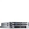
Overview The solution consists of two Dell PowerVault NX3500 systems and one Dell backup power supply (BPS). The two PowerVault NX3500 systems are also referred to as controller 0 and controller 1. The information in this document applies to both the PowerVault NX3500 systems and the BPS. Figure - Dell PowerVault NX3500 | Hardware Owner's Manual - Page 10
Dell PowerVault NX3500 Front-Panel system. NOTE: On ACPI-compliant operating systems, turning off the system using the power button causes the system to perform a graceful shutdown before power to the system is turned off. NOTE: To force an ungraceful shutdown during an emergency, always use the user - Dell PowerVault NX3500 | Hardware Owner's Manual - Page 11
operation. Lights amber when the system needs attention due to a problem. Connect USB devices to the system. The ports are USB 2.0-compliant. Two 3.5-inch hot-swappable SATA drives. A slide-out panel for system information including the Express Service tag, embedded NIC MAC address, and iDRAC6 - Dell PowerVault NX3500 | Hardware Owner's Manual - Page 12
Messages" on page 22 for information on specific status codes. The LCD backlight lights blue during normal operating conditions and lights amber to indicate an error condition. When the system is in standby mode, the LCD backlight switches off after five minutes of inactivity, and can be turned - Dell PowerVault NX3500 | Hardware Owner's Manual - Page 13
3 4 Item Buttons 1 Left 2 Select 3 Right 4 System ID Description Moves the cursor back in one-step increments. Turns the system ID mode on (LCD panel flashes blue) and off. Press quickly to toggle the system ID on and off. If the system hangs during POST, press and hold the system ID - Dell PowerVault NX3500 | Hardware Owner's Manual - Page 14
user-configurable information about the system. This screen is displayed during normal system operation when there are no status messages or errors present. When the system or Static IP to configure the network mode. If Static IP is selected by a Dell customer representative or a service technician. - Dell PowerVault NX3500 | Hardware Owner's Manual - Page 15
the MAC addresses for BMC, iSCSIn, or NETn. Displays the name of the Host, Model, or User String for the system. Displays the Asset tag or the Service tag for the system. Displays the power output of the system in BTU/hr or Watts. The display format can be configured in the Set home submenu - Dell PowerVault NX3500 | Hardware Owner's Manual - Page 16
for removal Off Drive ready for insertion or removal NOTE: The drive status indicator remains off until all hard drives are initialized after system power is applied. Drives are not ready for insertion or removal during this time. Blinks green, amber, and off Drive predicted failure Blinks - Dell PowerVault NX3500 | Hardware Owner's Manual - Page 17
PowerVault NX3500 Back-Panel Features and Indicators system. The ports are USB 2.0-compliant. Embedded 10/100/1000 NIC connectors. PCI Express (generation 2) expansion slot (full-height, half-length). Connector for attaching a system indicator extension cable that is used on a cable management - Dell PowerVault NX3500 | Hardware Owner's Manual - Page 18
during normal system operation. Both the systems management software and the identification buttons located on the front and back of the system can cause the indicator to flash blue to identify a particular system. Lights amber when the system needs attention due to a problem. Turns the system ID - Dell PowerVault NX3500 | Hardware Owner's Manual - Page 19
network. The NIC is connected to a valid network link at 1000 Mbps. The NIC is connected to a valid network link at 10/100 Mbps. Network supply is operational. When the system is on, it also indicates that the power supply is providing DC power to the system. • Amber-Indicates a problem with the - Dell PowerVault NX3500 | Hardware Owner's Manual - Page 20
Figure 1-7. Power Supply Status Indicator 1 1 Power supply status LED Dell Backup Power Supply Front-Panel Features Figure 1-8. Front-Panel Features 1 1 LED 2 2 power button 20 About Your Solution - Dell PowerVault NX3500 | Hardware Owner's Manual - Page 21
at start-up. Table 1-1. Visual Operating State Indicators LED Color and Pattern* Condition No LED display BPS power module off, grid power can be either present or not Solid green Grid power present, BPS power module on Blinking green No grid power, unit supporting load on battery (before - Dell PowerVault NX3500 | Hardware Owner's Manual - Page 22
. The LCD messages refer to events recorded in the System Event Log (SEL). For information on the SEL and configuring system management settings, see the systems management software documentation. NOTE: If your system fails to boot, press the System ID button for at least five seconds until an error - Dell PowerVault NX3500 | Hardware Owner's Manual - Page 23
failure Contact events. support. Remove AC power to the system for 10 seconds and restart the system. If the problem persists, see "Getting Help" on page 113. Ambient Temp Ambient temperature has See "Troubleshooting exceeds reached a point outside of System Cooling allowed range. the - Dell PowerVault NX3500 | Hardware Owner's Manual - Page 24
. Remove AC power to the system for 10 seconds and restart the system. If the problem persists, see "Getting Help" on page 113. Fan ## RPM exceeding range. Check fan. RPM of specified fan is outside of the intended operating range. See "Troubleshooting System Cooling Problems" on page 96. 24 - Dell PowerVault NX3500 | Hardware Owner's Manual - Page 25
fan in specified module is outside of intended operating range. See "Troubleshooting System Cooling Problems" on page 96. Fan redundancy The system is no longer lost. Check fan redundant. processor technical specifications outlined in your system's Getting Started Guide. About Your Solution 25 - Dell PowerVault NX3500 | Hardware Owner's Manual - Page 26
BIOS has reported a machine check error. Remove AC power to the system for 10 seconds and restart the system. If the problem persists, see "Getting Help" on page 113. Power Supply # Specified power supply See "Troubleshooting (### W) was removed or is missing Power Supply" on missing. from the - Dell PowerVault NX3500 | Hardware Owner's Manual - Page 27
is attached to the system, but it has lost its AC input. Check the AC power source for the specified power supply. If the problem persists, see "Troubleshooting Power in your system's Getting Started Guide. Power required > PSU wattage. Check PSU and config. The system configuration requires - Dell PowerVault NX3500 | Hardware Owner's Manual - Page 28
and then clear the SEL. Remove AC power to the system for 10 seconds and restart the system. If the problem persists, see "Getting Help" on page 113. Remove and reseat the PCIe expansion cards. If the problem persists, see "Troubleshooting an Expansion Card" on page 101. Remove and reseat the - Dell PowerVault NX3500 | Hardware Owner's Manual - Page 29
SEL. Remove AC power to the system for 10 seconds and restart the system. If the problem persists, see "Getting Help" on page 113. Remove and reseat the PCIe expansion cards. If the problem persists, see "Troubleshooting an Expansion Card" on page 101. See "Troubleshooting a Hard Drive" on page 100 - Dell PowerVault NX3500 | Hardware Owner's Manual - Page 30
or bad. Reseat the cable. If the problem persists, replace cable. If the problem persists, see "Getting Help" on page 113. Memory not detected. No memory was detected in the system. Inspect DIMMs. Install memory or reseat memory modules. See "Troubleshooting System Memory" on page 97. Memory - Dell PowerVault NX3500 | Hardware Owner's Manual - Page 31
see "Getting Help" on page 113. Remove AC power to the system for 10 seconds and restart the system. If the problem persists, see "Getting Help" on page 113. Remove AC power to the system for 10 seconds and restart the system. If the problem persists, see "Getting Help" on page 113. Remove AC power - Dell PowerVault NX3500 | Hardware Owner's Manual - Page 32
Power cycle AC. Keyboard controller failure. SMI System management initialization interrupt (SMI) failure. Power initialization system for 10 seconds and restart the system. If the problem persists, see "Getting Help" on page 113. See "Troubleshooting System Memory" on page 97. If the problem - Dell PowerVault NX3500 | Hardware Owner's Manual - Page 33
. Remove AC power to the system for 10 seconds and restart the system. If the problem persists, see "Troubleshooting System Memory" on page 97. Intrusion detected. Check chassis cover. System cover has been removed. Information only. LCD Log Full. Check SEL to review all Errors. LCD overflow - Dell PowerVault NX3500 | Hardware Owner's Manual - Page 34
hardware configuration or install higher-wattage power supplies, and then restart the system. NOTE: For the full name of an abbreviation or acronym used in this table, see the Glossary at support.dell.com/manuals. Solving Problems Described by LCD Status Messages The code and text on the LCD can - Dell PowerVault NX3500 | Hardware Owner's Manual - Page 35
appear on the screen to notify you of a possible problem with the system. NOTE: If you receive a system message not listed in the table, check the documentation for the application that is running when the message appears or the operating system's documentation for an explanation of the message and - Dell PowerVault NX3500 | Hardware Owner's Manual - Page 36
Alert! Power required exceeds PSU wattage. Check PSU and system configuration. The system configuration of processor, memory modules, and expansion cards may not be supported by the power supplies. Alert! Continuing system boot accepts the risk that system may power down without warning. If any - Dell PowerVault NX3500 | Hardware Owner's Manual - Page 37
cleared before the next boot. System reboot required for normal operation. System is in manufacturing Reboot to take the system mode. out of manufacturing mode. BIOS Update Remote BIOS update Attempt Failed! attempt failed. Retry the BIOS update. If the problem persists, see "Getting Help" on - Dell PowerVault NX3500 | Hardware Owner's Manual - Page 38
NIC=, in management tools. Management Shared NIC= Check the system management software or the System Setup program for NIC settings. If a problem is indicated, see "Troubleshooting a NIC" on page 93. Gate A20 failure. Faulty - Dell PowerVault NX3500 | Hardware Owner's Manual - Page 39
Local keyboard may not work because all user accessible USB ports are disabled. If operating locally, power cycle the system and enter system setup program to change settings. The USB ports are disabled in the system BIOS. Power down and restart the system from the power button, and then enter - Dell PowerVault NX3500 | Hardware Owner's Manual - Page 40
, optical drive, or hard drive. If the problem persists, see "Troubleshooting an Optical Drive" on page 99, and "Troubleshooting a Hard Drive" on page 100. Check the hard drive configuration settings in the System Setup program. If necessary, install the operating system on your hard drive. See your - Dell PowerVault NX3500 | Hardware Owner's Manual - Page 41
(pins 1 and 3) and reboot the system. See Figure 5-1 for jumper location. If the problem persists, see "Troubleshooting an Expansion Card" on page 101. " on page 67. Read fault. Requested sector not found. The operating system cannot Replace the optical medium, read from the hard drive, USB - Dell PowerVault NX3500 | Hardware Owner's Manual - Page 42
operation failed. Shutdown failure. General system error. The amount of Memory has been added or system memory has removed or a memory changed. module may be faulty. Corrective Actions Replace the hard drive. Ensure that the SAS backplane cables are properly connected. See "Troubleshooting - Dell PowerVault NX3500 | Hardware Owner's Manual - Page 43
or faulty chip. See "Troubleshooting the System Battery" on page 95. Time-of-day not Incorrect Time or Date set - please run settings; faulty system SETUP program. battery. Check the Time and Date settings. If the problem persists, replace the system battery. See "System Battery" on page 79 - Dell PowerVault NX3500 | Hardware Owner's Manual - Page 44
to system board replacement. Unified Server The iDRAC6 Enterprise card flash memory or BMC SPI flash may be corrupted. Configuration user documentation for more information. Restore the flash memory using the latest version on support.dell.com. See the iDRAC 6 User Guide for instructions on - Dell PowerVault NX3500 | Hardware Owner's Manual - Page 45
memory modules. modules or faulty keyboard or See "Troubleshooting mouse controller chip. System Memory" on page 97. If the problem persists, see "Getting Help" on page 113. Processor is not supported by Install a supported processor. the system. See "Processor" on page 73. Unsupported CPU - Dell PowerVault NX3500 | Hardware Owner's Manual - Page 46
to minimum frequencies to meet PSU wattage. System will component(s) are not supported with this power supply. If Energy Smart power system. system at the same time. You can also run the system on one power supply until you can obtain two power supplies of the same type. See "Troubleshooting - Dell PowerVault NX3500 | Hardware Owner's Manual - Page 47
and "Troubleshooting a Hard Drive" on page 100. NOTE: For the full name of an abbreviation or acronym used in this table, see the Glossary at support.dell.com/manuals. Warning Messages A warning message alerts you to a possible problem and prompts you to respond before the system continues a task - Dell PowerVault NX3500 | Hardware Owner's Manual - Page 48
and tools for configuring and managing your system, including those pertaining to the operating system, system management software, system updates, and system components that you purchased with your system. NOTE: Always check for updates on support.dell.com/manuals and read the updates first - Dell PowerVault NX3500 | Hardware Owner's Manual - Page 49
only perform troubleshooting and simple repairs as authorized in your product documentation, or as directed by the online or telephone service and support team. Damage due to servicing that is not authorized by Dell is not covered by your warranty. Read and follow the safety instructions that came - Dell PowerVault NX3500 | Hardware Owner's Manual - Page 50
Figure 2-1. Inside the System 11 10 1 2 3 9 8 7 1 cooling shroud 3 expansion-card riser 5 memory modules (6) 7 control panel board 9 hard drives (2) 11 power supply shroud 4 5 6 2 power supply bays (2) 4 heat sink/processor 6 optical drive 8 display module 10 system cooling fans (5) 50 - Dell PowerVault NX3500 | Hardware Owner's Manual - Page 51
the left end of the bezel away from the front panel. 4 Unhook the right end of the bezel and pull the bezel away from the system. Figure 2-2. Removing and Installing the Front Bezel 3 2 1 4 1 release latch 3 front bezel 2 keylock 4 hinge tab To replace the bezel, hook the right end of the bezel - Dell PowerVault NX3500 | Hardware Owner's Manual - Page 52
or telephone service and support team. Damage due to servicing that is not authorized by Dell is not covered by your warranty. Read and follow the safety instructions that came with the product. Opening the System 1 Turn off the system and attached peripherals, and disconnect the system from the - Dell PowerVault NX3500 | Hardware Owner's Manual - Page 53
the cover onto the chassis and offset it slightly toward the back of the system, so that the two pins on the back edge of the cover fit over the corresponding slots it snaps in position. 3 Rotate the latch release lock in a clockwise direction to secure the cover. Installing System Components 53 - Dell PowerVault NX3500 | Hardware Owner's Manual - Page 54
or telephone service and support team. Damage due to servicing that is not authorized by Dell is not covered by your warranty. Read and follow the safety instructions that came with the product. 1 Turn off the system, including any attached peripherals, and disconnect the system from its electrical - Dell PowerVault NX3500 | Hardware Owner's Manual - Page 55
Figure 2-4. Removing and Installing the Optical Drive 1 2 3 7 4 6 5 1 data cable 3 optical drive 5 metal standoffs (2) 7 metal standoffs with notches (2) 2 power cable 4 release latch 6 notches (2) Installing System Components 55 - Dell PowerVault NX3500 | Hardware Owner's Manual - Page 56
or telephone service and support team. Damage due to servicing that is not authorized by Dell is not covered by your warranty. Read and follow the safety instructions that came with the product. 1 Turn off the system, including any attached peripherals, and disconnect the system from its electrical - Dell PowerVault NX3500 | Hardware Owner's Manual - Page 57
-Drive Carrier CAUTION: Ensure that your operating system supports hot-swap drive installation. See the documentation supplied with the operating system. 1 If applicable, remove the front bezel. See "Front Bezel" on page 51. 2 Using the RAID management software, prepare the hard drive for removal - Dell PowerVault NX3500 | Hardware Owner's Manual - Page 58
by the online or telephone service and support team. Damage due to servicing that is not authorized by Dell is not covered by your warranty. Read and follow the safety instructions that came with the product. CAUTION: Ensure that your operating system supports hot-swap drive installation. See - Dell PowerVault NX3500 | Hardware Owner's Manual - Page 59
the hard drive from the carrier. See Figure 2-6. Figure 2-6. Removing and Installing a Hard Drive 1 2 4 1 screws (4) 3 SAS/SATA screw hole 3 2 hard drive 4 hard-drive carrier Installing System Components 59 - Dell PowerVault NX3500 | Hardware Owner's Manual - Page 60
or telephone service and support team. Damage due to servicing that is not authorized by Dell is not covered by your warranty. Read and follow the safety instructions that came with the product. 1 Turn off the system, including any attached peripherals, and disconnect the system from the electrical - Dell PowerVault NX3500 | Hardware Owner's Manual - Page 61
card 4 expansion-card riser 6 Unpack the new NIC card and prepare it for installation. For instructions, see the documentation accompanying the card. 7 Holding the expansion NIC card by its edges, position the 2-7. 10 Connect any cables to the expansion NIC card. Installing System Components 61 - Dell PowerVault NX3500 | Hardware Owner's Manual - Page 62
, or as directed by the online or telephone service and support team. Damage due to servicing that is not authorized by Dell is not covered by your warranty. Read and follow the safety instructions that came with the product. CAUTION: Never operate your system with the cooling shroud removed. The - Dell PowerVault NX3500 | Hardware Owner's Manual - Page 63
support team. Damage due to servicing that is not authorized by Dell is not covered by your warranty. Read and follow the safety instructions that came with the product. 1 Orient the cooling shroud with the numbered fan bays as a guide. 2 Align the cooling shroud posts with the slots on the system - Dell PowerVault NX3500 | Hardware Owner's Manual - Page 64
or telephone service and support team. Damage due to servicing that is not authorized by Dell is not covered by your warranty. Read and follow the safety instructions that came with the product. 1 Turn off the system, including any attached peripherals, and disconnect the system from the electrical - Dell PowerVault NX3500 | Hardware Owner's Manual - Page 65
Figure 2-9. Removing and Installing the Integrated Storage Controller Card 1 2 4 3 1 integrated storage controller card connector 3 release tab 2 integrated storage controller card 4 alignment guides (2) Installing System Components 65 - Dell PowerVault NX3500 | Hardware Owner's Manual - Page 66
or telephone service and support team. Damage due to servicing that is not authorized by Dell is not covered by your warranty. Read and follow the safety instructions that came with the product. 1 Turn off the system, including any attached peripherals, and disconnect the system from the electrical - Dell PowerVault NX3500 | Hardware Owner's Manual - Page 67
or telephone service and support team. Damage due to servicing that is not authorized by Dell is not covered by your warranty. Read and follow the safety instructions that came with the product. 1 Turn off the system, including any attached peripherals, and disconnect the system from the electrical - Dell PowerVault NX3500 | Hardware Owner's Manual - Page 68
step 8 of this procedure to install the remaining memory modules. 9 Replace the cooling shroud. See "Installing the Cooling Shroud" on page 63. 10 Close the system. See "Closing the System" on page 53. 68 Installing - Dell PowerVault NX3500 | Hardware Owner's Manual - Page 69
attempt to operate the system without the cooling fan. CAUTION: Many repairs may only be done by a certified service technician. You should only perform troubleshooting and simple repairs as authorized in your product documentation, or as directed by the online or telephone service and support team - Dell PowerVault NX3500 | Hardware Owner's Manual - Page 70
Remove the cooling shroud or power distribution board shroud as applicable. See "Cooling Shroud" on page 62. 4 Disconnect the fan's power cable from the system board. See Figure 2-11. 5 Grasp the fan and slide it away from the fan assembly. See Figure 2-11. Figure 2-11. Removing and Installing a Fan - Dell PowerVault NX3500 | Hardware Owner's Manual - Page 71
or telephone service and support team. Damage due to servicing that is not authorized by Dell is not covered by your warranty. Read and follow the safety instructions that came with the product. 1 Turn off the system, including any attached peripherals, and disconnect the system from the electrical - Dell PowerVault NX3500 | Hardware Owner's Manual - Page 72
opening. See Figure 2-12. 8 Align the front edge of the card with the two front plastic retention standoffs next to the iDRAC6 connector on the system board, and lower the card into place. See Figure 2-12. When the front of the card is fully seated, the plastic standoffs snap over the - Dell PowerVault NX3500 | Hardware Owner's Manual - Page 73
warranty. Read and follow the safety instructions that came with the product. 1 Prior to upgrading your system, download the latest system BIOS version on support.dell.com. 2 Turn off the system, including any attached peripherals, and disconnect the system from the electrical outlet. 3 Open the - Dell PowerVault NX3500 | Hardware Owner's Manual - Page 74
. CAUTION: Be careful not to bend any of the pins on the ZIF socket when removing the processor. Bending the pins can permanently damage the system board. 74 Installing - Dell PowerVault NX3500 | Hardware Owner's Manual - Page 75
Figure 2-14. Removing and Installing a Processor 1 6 2 3 5 1 processor 3 socket key 5 processor shield 4 2 notch in processor 4 ZIF socket 6 socket-release lever Installing System Components 75 - Dell PowerVault NX3500 | Hardware Owner's Manual - Page 76
troubleshooting and simple repairs as authorized in your product documentation, or as directed by the online or telephone service and support team. Damage due to servicing that is not authorized by Dell is not covered by your warranty. Read and follow the safety instructions the system board or - Dell PowerVault NX3500 | Hardware Owner's Manual - Page 77
or telephone service and support team. Damage due to servicing that is not authorized by Dell is not covered by your warranty. Read and follow the safety instructions that came with the product. CAUTION: The system requires one power supply for normal operation. On power-redundant systems, remove - Dell PowerVault NX3500 | Hardware Owner's Manual - Page 78
cables. NOTE: You may have to unlatch and lift the optional cable management arm if it interferes with power-supply removal. For information about the cable management arm, see the system's rack documentation. 3 Press the release latch and pull the power supply straight out to release it from the - Dell PowerVault NX3500 | Hardware Owner's Manual - Page 79
or telephone service and support team. Damage due to servicing that is not authorized by Dell is not covered by your warranty. Read and follow the safety instructions that came with the product. 1 Turn off the system, including any attached peripherals, and disconnect the system from the electrical - Dell PowerVault NX3500 | Hardware Owner's Manual - Page 80
it snaps into place. 7 Close the system. See "Closing the System" on page 53. 8 Reconnect the system to its electrical outlet and turn the system on, including any attached peripherals. 9 Enter the System Setup program to confirm that the battery is operating properly. 10 Enter the correct time and - Dell PowerVault NX3500 | Hardware Owner's Manual - Page 81
service and support team. Damage due to servicing that is not authorized by Dell is not covered by your warranty. Read and follow the safety instructions that came with the product. 1 If installed, remove the front bezel. See "Front Bezel" on page 51. 2 Turn off the system and attached peripherals - Dell PowerVault NX3500 | Hardware Owner's Manual - Page 82
Figure 2-17. Removing and Installing the Control Panel Assembly 2 3 1 4 5 6 8 1 display module cable 3 control panel data cable 5 mounting screws 7 front panel screw (2) 7 2 control panel board 4 internal USB Connector 6 power cable 8 LCD display module 82 Installing System Components - Dell PowerVault NX3500 | Hardware Owner's Manual - Page 83
the online or telephone service and support team. Damage due to servicing that is not authorized by Dell is not covered by your warranty. Read and follow the safety instructions that came with the product. 1 Turn off the system and attached peripherals, and disconnect the system from the electrical - Dell PowerVault NX3500 | Hardware Owner's Manual - Page 84
on a work surface. Figure 2-18. Removing and Installing a SAS Backplane 1 2 3 4 5 1 backplane retention latches (2) 3 SAS A cable 5 SAS B cable 2 SAS backplane power cable 4 SAS backplane 84 Installing System Components - Dell PowerVault NX3500 | Hardware Owner's Manual - Page 85
only perform troubleshooting and simple repairs as authorized in your product documentation, or as directed by the online or telephone service and support team. Damage due to servicing that is not authorized by Dell is not covered by your warranty. Read and follow the safety instructions that came - Dell PowerVault NX3500 | Hardware Owner's Manual - Page 86
troubleshooting and simple repairs as authorized in your product documentation, or as directed by the online or telephone service and support team. Damage due to servicing that is not authorized by Dell is not covered by your warranty. Read and follow the safety instructions system board (see "System - Dell PowerVault NX3500 | Hardware Owner's Manual - Page 87
Figure 2-19. Removing and Installing the Power Distribution Board 1 6 2 5 4 3 1 screws (2) 3 power-distribution board 5 fan module cable connectors (2) 2 power supply cables (2) 4 standoffs (2) 6 fan module power cables (2) Installing System Components 87 - Dell PowerVault NX3500 | Hardware Owner's Manual - Page 88
only perform troubleshooting and simple repairs as authorized in your product documentation, or as directed by the online or telephone service and support team. Damage due to servicing that is not authorized by Dell is not covered by your warranty. Read and follow the safety instructions that came - Dell PowerVault NX3500 | Hardware Owner's Manual - Page 89
only perform troubleshooting and simple repairs as authorized in your product documentation, or as directed by the online or telephone service and support team. Damage due to servicing that is not authorized by Dell is not covered by your warranty. Read and follow the safety instructions that came - Dell PowerVault NX3500 | Hardware Owner's Manual - Page 90
modules, record the memory module socket locations. 10 Carefully route any loose cables away from the edges of the system board. 11 Remove the nine screws securing the system board to the chassis and then slide the system board assembly toward the front of the chassis. CAUTION: Do not lift the - Dell PowerVault NX3500 | Hardware Owner's Manual - Page 91
troubleshooting and simple repairs as authorized in your product documentation, or as directed by the online or telephone service and support team. Damage due to servicing that is not authorized by Dell is not covered by your warranty. Read and follow the safety instructions on the system board): • - Dell PowerVault NX3500 | Hardware Owner's Manual - Page 92
an Expansion NIC Card" on page 60. 13 Replace the cooling shroud. See "Installing the Cooling Shroud" on page 63. 14 Close the system. See "Closing the System" on page 53. 15 Reconnect the system to its electrical outlet and turn the system on, including any attached peripherals. 92 Installing - Dell PowerVault NX3500 | Hardware Owner's Manual - Page 93
due to servicing that is not authorized by Dell is not covered by your warranty. Read and follow the safety instructions that came with the product. Troubleshooting System Startup Failure If your system halts during startup prior to video output, especially after installing an operating system or - Dell PowerVault NX3500 | Hardware Owner's Manual - Page 94
only perform troubleshooting and simple repairs as authorized in your product documentation, or as directed by the online or telephone service and support team. Damage due to servicing that is not authorized by Dell is not covered by your warranty. Read and follow the safety instructions that came - Dell PowerVault NX3500 | Hardware Owner's Manual - Page 95
"Getting Help" on page 113. NOTE: Some software may cause the system time to speed up or slow down. If the system seems to operate normally except for the time kept in the System Setup program, the problem may be caused by software rather than by a defective battery. Troubleshooting Your System 95 - Dell PowerVault NX3500 | Hardware Owner's Manual - Page 96
113. Troubleshooting System Cooling Problems CAUTION: Many repairs may only be done by a certified service technician. You should only perform troubleshooting and simple repairs as authorized in your product documentation, or as directed by the online or telephone service and support team. Damage - Dell PowerVault NX3500 | Hardware Owner's Manual - Page 97
69. 7 Restart the system. If the problem is resolved, close the system. See "Closing the System" on page 53. If the replacement fan does not operate, see "Getting Help" on page 113. Troubleshooting System Memory CAUTION: Many repairs may only be done by a certified service technician. You should - Dell PowerVault NX3500 | Hardware Owner's Manual - Page 98
Diagnostics" on page 105. If diagnostics indicates a fault, follow the corrective actions provided by the diagnostic program. 2 If the system is not operational, turn off the system and attached peripherals, and unplug the system from the power source. Wait at least 10 seconds and then reconnect the - Dell PowerVault NX3500 | Hardware Owner's Manual - Page 99
only perform troubleshooting and simple repairs as authorized in your product documentation, or as directed by the online or telephone service and support team. Damage due to servicing that is not authorized by Dell is not covered by your warranty. Read and follow the safety instructions that came - Dell PowerVault NX3500 | Hardware Owner's Manual - Page 100
service and support team. Damage due to servicing that is not authorized by Dell is not covered by your warranty. Read and follow the safety instructions that came with the product CAUTION: This troubleshooting utility and allow the system to boot to the operating system. 3 Ensure that the - Dell PowerVault NX3500 | Hardware Owner's Manual - Page 101
or telephone service and support team. Damage due to servicing that is not authorized by Dell is not covered by your warranty. Read and follow the safety instructions that came with the product NOTE: When troubleshooting an expansion card, see the documentation for your operating system and the - Dell PowerVault NX3500 | Hardware Owner's Manual - Page 102
by Dell is not covered by your warranty. Read and follow the safety instructions that came with the product 1 Turn off the system and attached peripherals, and disconnect the system from the electrical outlet. 2 Open the system. See "Opening the System" on page 52. 102 Troubleshooting Your System - Dell PowerVault NX3500 | Hardware Owner's Manual - Page 103
reinstall the expansion card that you removed. See "Replacing an Expansion NIC Card" on page 60. 9 Restart the system. 10 Run the appropriate online diagnostic test. See "Running the System Diagnostics" on page 105. If the tests fail, see "Getting Help" on page 113. Troubleshooting Your System 103 - Dell PowerVault NX3500 | Hardware Owner's Manual - Page 104
104 Troubleshooting Your System - Dell PowerVault NX3500 | Hardware Owner's Manual - Page 105
problem yourself, service and support personnel can use diagnostics test results to help you solve the problem. Embedded System Diagnostics Features The system problems encountered during testing When to Use the Embedded System Diagnostics If a major component or device in the system does not operate - Dell PowerVault NX3500 | Hardware Owner's Manual - Page 106
Option Express Test Extended Test Custom Test Information Function Performs a quick check of the system. This option runs device tests that do not require user interaction. Performs a more thorough check of the system. This test can take an hour or longer. Tests a particular device. Displays test - Dell PowerVault NX3500 | Hardware Owner's Manual - Page 107
, component, or test. • Configuration - Displays basic configuration information about the currently selected device. • Parameters - Displays parameters that you can set for the test. Running the System Diagnostics 107 - Dell PowerVault NX3500 | Hardware Owner's Manual - Page 108
108 Running the System Diagnostics - Dell PowerVault NX3500 | Hardware Owner's Manual - Page 109
jumpers and switches and describes the connectors on the system board. System Board Jumpers Figure 5-1 shows the location of the configuration jumpers on the system board. Table 5-1 lists the jumper settings. Table 5-1. System Board Jumper Settings Jumper Setting Description PWRD_EN (default - Dell PowerVault NX3500 | Hardware Owner's Manual - Page 110
System Board Connectors Figure 5-1. System Board Connectors 1 23 4 20 19 18 17 16 15 14 13 12 5 11 10 9 8 7 6 110 Jumpers and Connectors - Dell PowerVault NX3500 | Hardware Owner's Manual - Page 111
iDRAC6 Enterprise card connector 5 CPU Processor socket 6 FAN1 System fan 1 connector 7 FAN2 System fan 2 connector 8 FAN3 System fan 3 connector 9 5 Memory module slot 5 -card cable connector 20 PCIE-G2-X4 Internal storage controller card connector Jumpers and Connectors 111 - Dell PowerVault NX3500 | Hardware Owner's Manual - Page 112
: See "Protecting Against Electrostatic Discharge" in the safety instructions that came with the system. 1 Turn off the system, including any attached peripherals, and disconnect the system from the electrical outlet. 2 Open the system. See "Opening the System" on page 52. 3 Remove the jumper plug - Dell PowerVault NX3500 | Hardware Owner's Manual - Page 113
, or Dell product catalog. Dell provides several online and telephone-based support and service options. Availability varies by country and product, and some services may not be available in your area. To contact Dell for sales, technical support, or customer service issues: 1 Visit support.dell.com - Dell PowerVault NX3500 | Hardware Owner's Manual - Page 114
114 Getting Help - Dell PowerVault NX3500 | Hardware Owner's Manual - Page 115
panel features, 12 removing, 81 cooling fan replacing, 71 cooling fans, 69 troubleshooting, 97 cooling shroud installing, 63 removing, 62 cover closing, 53 opening, 52 D damaged systems troubleshooting, 94 Dell contacting, 113 diagnostics advanced testing options, 106 when to use, 105 DIMMs See - Dell PowerVault NX3500 | Hardware Owner's Manual - Page 116
cooling shroud, 63 hard drive (hot-pluggable), 58 optical drive, 54 processor, 76 SAS backplane board, 85 SAS controller, 66 system board, 89 J jumpers (system board), 109 L LCD panel features, 12 menus, 14 M memory troubleshooting, 97 memory modules (DIMMs) configuring, 67 messages status LCD, 22 - Dell PowerVault NX3500 | Hardware Owner's Manual - Page 117
drive. See hard drive. slots See expansion slots. support contacting Dell, 113 system closing, 53 opening, 52 system board installing, 91 jumpers, 109 removing, 89 system cooling troubleshooting, 96 system messages, 35 T telephone numbers, 113 troubleshooting CD drive, 99 cooling fan, 97 damaged - Dell PowerVault NX3500 | Hardware Owner's Manual - Page 118
hard drive, 100 memory, 97 NIC, 93 power supply, 96 processor, 102 system cooling, 96 wet system, 102 U upgrades processor, 73 USB device back-panel connectors, 17 W warning messages, 47 warranty, 48 wet system troubleshooting, 102 Index 118
-
 1
1 -
 2
2 -
 3
3 -
 4
4 -
 5
5 -
 6
6 -
 7
7 -
8
-
9
-
10
-
11
-
12
-
13
-
14
-
15
-
16
-
17
-
18
-
19
-
20
-
21
-
22
-
23
-
24
-
25
-
26
-
27
-
28
-
29
-
30
-
31
-
32
-
33
-
34
-
35
-
36
-
37
-
38
-
39
-
40
-
41
-
42
-
43
-
44
-
45
-
46
-
47
-
48
-
49
-
50
-
51
-
52
-
53
-
54
-
55
-
56
-
57
-
58
-
59
-
60
-
61
-
62
-
63
-
64
-
65
-
66
-
67
-
68
-
69
-
70
-
71
-
72
-
73
-
74
-
75
-
76
-
77
-
78
-
79
-
80
-
81
-
82
-
83
-
84
-
85
-
86
-
87
-
88
-
89
-
90
-
91
-
92
-
93
-
94
-
95
-
96
-
97
-
98
-
99
-
100
-
101
-
102
-
103
-
104
-
105
-
106
-
107
-
108
-
109
-
110
-
111
-
112
-
113
-
114
-
115
-
116
-
117
-
118
 |
 |

Dell PowerVault
NX3500 Systems
Hardware Owner’s
Manual
Regulatory Model: E07S Series,
DELL500WLV, and DELL500WHV
Regulatory Type: E07S002