Dell PowerVault NX3500 Hardware Owner's Manual - Page 62
Cooling Shroud, Removing the Cooling Shroud
 |
View all Dell PowerVault NX3500 manuals
Add to My Manuals
Save this manual to your list of manuals |
Page 62 highlights
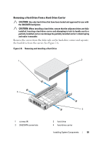
11 Close the system. See "Closing the System" on page 53. 12 Reconnect the system to its electrical outlet and turn the system on, including any attached peripherals. Cooling Shroud The system board shroud covers the processor, heat sink, and memory modules, and provides air flow to these components. Airflow is facilitated by the cooling fan modules, which are positioned directly beneath the cooling shroud. The power distribution board shroud covers the power distribution board behind the power supply bay. Removing the Cooling Shroud WARNING: The memory modules and heat sink can get very hot during normal operation. Ensure that the memory modules and heat sink have had sufficient time to cool before you touch it. CAUTION: Many repairs may only be done by a certified service technician. You should only perform troubleshooting and simple repairs as authorized in your product documentation, or as directed by the online or telephone service and support team. Damage due to servicing that is not authorized by Dell is not covered by your warranty. Read and follow the safety instructions that came with the product. CAUTION: Never operate your system with the cooling shroud removed. The system may get overheated quickly, resulting in shutdown of the system and loss of data. 1 Turn off the system, including any attached peripherals, and disconnect the system from the electrical outlet. 2 Open the system. See "Opening and Closing the System" on page 52. 3 Remove the SAS backplane cables routed over the shroud from the system board. 4 Hold the touch points and gently lift the shroud straight up and away from the system board. See Figure 2-8. 62 Installing System Components
-
 1
1 -
2
-
3
-
4
-
5
-
6
-
7
-
8
-
9
-
10
-
11
-
12
-
13
-
14
-
15
-
16
-
17
-
18
-
19
-
20
-
21
-
22
-
23
-
24
-
25
-
26
-
27
-
28
-
29
-
30
-
31
-
32
-
33
-
34
-
35
-
36
-
37
-
38
-
39
-
40
-
41
-
42
-
43
-
44
-
45
-
46
-
47
-
48
-
49
-
50
-
51
-
52
-
53
-
54
-
55
-
56
-
 57
57 -
 58
58 -
 59
59 -
 60
60 -
 61
61 -
 62
62 -
 63
63 -
 64
64 -
 65
65 -
 66
66 -
 67
67 -
68
-
69
-
70
-
71
-
72
-
73
-
74
-
75
-
76
-
77
-
78
-
79
-
80
-
81
-
82
-
83
-
84
-
85
-
86
-
87
-
88
-
89
-
90
-
91
-
92
-
93
-
94
-
95
-
96
-
97
-
98
-
99
-
100
-
101
-
102
-
103
-
104
-
105
-
106
-
107
-
108
-
109
-
110
-
111
-
112
-
113
-
114
-
115
-
116
-
117
-
118
 |
 |