Dell PowerVault NX3500 Hardware Owner's Manual - Page 82
Removing and Installing the Control Panel Assembly, internal USB Connector
 |
View all Dell PowerVault NX3500 manuals
Add to My Manuals
Save this manual to your list of manuals |
Page 82 highlights
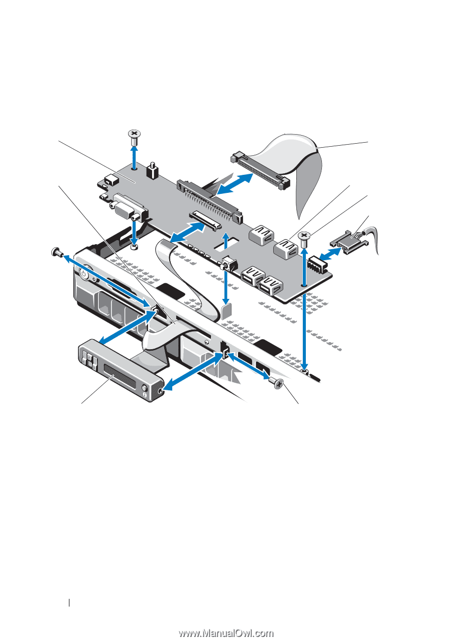
Figure 2-17. Removing and Installing the Control Panel Assembly 2 3 1 4 5 6 8 1 display module cable 3 control panel data cable 5 mounting screws 7 front panel screw (2) 7 2 control panel board 4 internal USB Connector 6 power cable 8 LCD display module 82 Installing System Components
-
 1
1 -
2
-
3
-
4
-
5
-
6
-
7
-
8
-
9
-
10
-
11
-
12
-
13
-
14
-
15
-
16
-
17
-
18
-
19
-
20
-
21
-
22
-
23
-
24
-
25
-
26
-
27
-
28
-
29
-
30
-
31
-
32
-
33
-
34
-
35
-
36
-
37
-
38
-
39
-
40
-
41
-
42
-
43
-
44
-
45
-
46
-
47
-
48
-
49
-
50
-
51
-
52
-
53
-
54
-
55
-
56
-
57
-
58
-
59
-
60
-
61
-
62
-
63
-
64
-
65
-
66
-
67
-
68
-
69
-
70
-
71
-
72
-
73
-
74
-
75
-
76
-
 77
77 -
 78
78 -
 79
79 -
 80
80 -
 81
81 -
 82
82 -
 83
83 -
 84
84 -
 85
85 -
 86
86 -
 87
87 -
88
-
89
-
90
-
91
-
92
-
93
-
94
-
95
-
96
-
97
-
98
-
99
-
100
-
101
-
102
-
103
-
104
-
105
-
106
-
107
-
108
-
109
-
110
-
111
-
112
-
113
-
114
-
115
-
116
-
117
-
118
 |
 |
82
Installing System Components
Figure 2-17.
Removing and Installing the Control Panel Assembly
1
display module cable
2
control panel board
3
control panel data cable
4
internal USB Connector
5
mounting screws
6
power cable
7
front panel screw (2)
8
LCD display module
1
3
5
2
6
7
8
4