Dell PowerVault NX3500 Hardware Owner's Manual - Page 67
General Memory Module Installation Guidelines, Replacing Memory Modules, WARNING, CAUTION
 |
View all Dell PowerVault NX3500 manuals
Add to My Manuals
Save this manual to your list of manuals |
Page 67 highlights
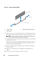
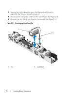
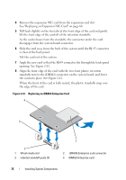
General Memory Module Installation Guidelines To ensure optimal performance of your system, observe the following general guidelines when configuring your system memory. NOTE: Memory configurations that fail to observe these guidelines can prevent your system from starting and producing any video output. • Except for memory channels that are unused, all populated memory channels must have identical configurations. • Memory modules are installed in the numeric order of the sockets beginning with 1 to 6. Replacing Memory Modules WARNING: The memory modules are hot to touch for some time after the system has been powered down. Allow time for the memory modules to cool before handling them. Handle the memory modules by the card edges and avoid touching the components on the memory module. CAUTION: Many repairs may only be done by a certified service technician. You should only perform troubleshooting and simple repairs as authorized in your product documentation, or as directed by the online or telephone service and support team. Damage due to servicing that is not authorized by Dell is not covered by your warranty. Read and follow the safety instructions that came with the product. 1 Turn off the system, including any attached peripherals, and disconnect the system from the electrical outlet. 2 Open the system. See "Opening the System" on page 52. 3 Remove the cooling shroud. See "Removing the Cooling Shroud" on page 62. 4 Locate the memory module sockets. See Figure 5-1. 5 Press down and out on the ejectors on each end of the socket until the memory module pops out of the socket. See Figure 2-10. Handle each memory module only on either card edge, making sure not to touch the middle of the memory module. Installing System Components 67
-
 1
1 -
2
-
3
-
4
-
5
-
6
-
7
-
8
-
9
-
10
-
11
-
12
-
13
-
14
-
15
-
16
-
17
-
18
-
19
-
20
-
21
-
22
-
23
-
24
-
25
-
26
-
27
-
28
-
29
-
30
-
31
-
32
-
33
-
34
-
35
-
36
-
37
-
38
-
39
-
40
-
41
-
42
-
43
-
44
-
45
-
46
-
47
-
48
-
49
-
50
-
51
-
52
-
53
-
54
-
55
-
56
-
57
-
58
-
59
-
60
-
61
-
 62
62 -
 63
63 -
 64
64 -
 65
65 -
 66
66 -
 67
67 -
 68
68 -
 69
69 -
 70
70 -
 71
71 -
 72
72 -
73
-
74
-
75
-
76
-
77
-
78
-
79
-
80
-
81
-
82
-
83
-
84
-
85
-
86
-
87
-
88
-
89
-
90
-
91
-
92
-
93
-
94
-
95
-
96
-
97
-
98
-
99
-
100
-
101
-
102
-
103
-
104
-
105
-
106
-
107
-
108
-
109
-
110
-
111
-
112
-
113
-
114
-
115
-
116
-
117
-
118
 |
 |