Dell PowerVault NX3500 Hardware Owner's Manual - Page 83
Installing the Control Panel Board Assembly and the Control Panel Display Module, SAS Backplane
 |
View all Dell PowerVault NX3500 manuals
Add to My Manuals
Save this manual to your list of manuals |
Page 83 highlights
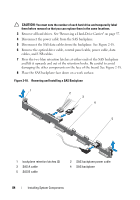
Installing the Control Panel Board Assembly and the Control Panel Display Module CAUTION: Many repairs may only be done by a certified service technician. You should only perform troubleshooting and simple repairs as authorized in your product documentation, or as directed by the online or telephone service and support team. Damage due to servicing that is not authorized by Dell is not covered by your warranty. Read and follow the safety instructions that came with the product. 1 Affix the replacement panel to the front of the display module. 2 Align the slot in the control panel board with the standoff on the system chassis and secure with the two screws. See Figure 2-17. For LED control panel, skip step 4. 3 Connect the display module cable to the control panel board. 4 Connect the USB and control panel cables to the control panel board. 5 Close the system. See "Closing the System" on page 53. 6 If applicable, replace the front bezel. See "Front Bezel" on page 51. 7 Reconnect the system to the power source and turn on the system and attached peripherals. SAS Backplane Removing the SAS Backplane CAUTION: Many repairs may only be done by a certified service technician. You should only perform troubleshooting and simple repairs as authorized in your product documentation, or as directed by the online or telephone service and support team. Damage due to servicing that is not authorized by Dell is not covered by your warranty. Read and follow the safety instructions that came with the product. 1 Turn off the system and attached peripherals, and disconnect the system from the electrical outlet. 2 Open the system. See "Opening the System" on page 52. CAUTION: To prevent damage to the drives and backplane, you must remove the hard drives from the system before removing the backplane. Installing System Components 83
-
 1
1 -
2
-
3
-
4
-
5
-
6
-
7
-
8
-
9
-
10
-
11
-
12
-
13
-
14
-
15
-
16
-
17
-
18
-
19
-
20
-
21
-
22
-
23
-
24
-
25
-
26
-
27
-
28
-
29
-
30
-
31
-
32
-
33
-
34
-
35
-
36
-
37
-
38
-
39
-
40
-
41
-
42
-
43
-
44
-
45
-
46
-
47
-
48
-
49
-
50
-
51
-
52
-
53
-
54
-
55
-
56
-
57
-
58
-
59
-
60
-
61
-
62
-
63
-
64
-
65
-
66
-
67
-
68
-
69
-
70
-
71
-
72
-
73
-
74
-
75
-
76
-
77
-
 78
78 -
 79
79 -
 80
80 -
 81
81 -
 82
82 -
 83
83 -
 84
84 -
 85
85 -
 86
86 -
 87
87 -
 88
88 -
89
-
90
-
91
-
92
-
93
-
94
-
95
-
96
-
97
-
98
-
99
-
100
-
101
-
102
-
103
-
104
-
105
-
106
-
107
-
108
-
109
-
110
-
111
-
112
-
113
-
114
-
115
-
116
-
117
-
118
 |
 |