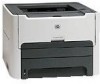
HP 1320 Service Manual - Page 11
List of s - laserjet laser printer
 |
UPC - 829160406831
View all HP 1320 manuals
Add to My Manuals
Save this manual to your list of manuals |
Page 11 highlights
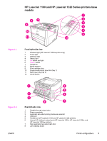
List of figures ENWW Figure 1-1. Figure 1-2. Figure 2-1. Figure 2-2. Figure 2-3. Figure 2-4. Figure 2-5. Figure 5-1. Figure 5-2. Figure 5-3. Figure 5-4. Figure 5-5. Figure 5-6. Figure 5-7. Figure 5-8. Figure 5-9. Figure 5-10. Figure 5-11. Figure 5-12. Figure 5-13. Figure 6-1. Figure 6-2. Figure 6-3. Figure 6-4. Figure 6-5. Figure 6-6. Figure 6-7. Figure 6-8. Figure 6-9. Figure 6-10. Figure 6-11. Figure 6-12. Figure 6-13. Figure 6-14. Figure 6-15. Figure 6-16. Figure 6-17. Figure 6-18. Figure 6-19. Figure 6-20. Figure 6-21. Figure 6-22. Figure 6-23. Figure 6-24. Figure 6-25. Figure 6-26. Front/right-side view 3 Rear/left-side view 3 USB connection 22 Parallel connection 22 Network connection 23 Wireless connection, infrastructure mode 23 Wireless connection, ad hoc mode 23 Block diagram 66 Cross-section of printer 67 Engine control system 70 Engine control system circuit diagram 71 Laser/scanner system 72 Pickup/feed/delivery system 74 Image-formation system 75 Primary charging 75 Developing...76 Transfer...76 Separation...77 Fusing...77 Drum cleaning 78 Removing the left-side cover (1 of 2 82 Removing the left-side cover (2 of 2 83 Removing the right-side cover (1 of 2 84 Removing the right-side cover (2 of 2 85 Removing the back cover (1 of 2 86 Removing the back cover (2 of 2 87 Reinstalling the back cover 88 Removing the duplexer tray 89 Removing the top cover (1 of 3 90 Removing the top cover (2 of 3 91 Removing the top cover (3 of 3 92 Removing the control panel (1 of 2 93 Removing the control panel (2 of 2 94 Removing the formatter 95 Removing the memory-tag-reader assembly (1 of 2 97 Removing the memory-tag-reader assembly (2 of 2 98 Removing the duplex-drive PCA (1 of 2 99 Removing the duplex-drive PCA (2 of 2 100 Removing the fan (1 of 2 101 Removing the duplex-drive gears/face-down gears 103 Duplex-drive gears (HP LaserJet 1320 Series printers 104 Face-down gears (HP LaserJet 1160 printers 105 Removing the duplex solenoid 106 Removing the fuser (1 of 10 107 Removing the fuser (2 of 10 108 Removing the fuser (3 of 10 109 ix
-
 1
1 -
2
-
3
-
4
-
5
-
 6
6 -
 7
7 -
 8
8 -
 9
9 -
 10
10 -
 11
11 -
 12
12 -
 13
13 -
 14
14 -
 15
15 -
 16
16 -
17
-
18
-
19
-
20
-
21
-
22
-
23
-
24
-
25
-
26
-
27
-
28
-
29
-
30
-
31
-
32
-
33
-
34
-
35
-
36
-
37
-
38
-
39
-
40
-
41
-
42
-
43
-
44
-
45
-
46
-
47
-
48
-
49
-
50
-
51
-
52
-
53
-
54
-
55
-
56
-
57
-
58
-
59
-
60
-
61
-
62
-
63
-
64
-
65
-
66
-
67
-
68
-
69
-
70
-
71
-
72
-
73
-
74
-
75
-
76
-
77
-
78
-
79
-
80
-
81
-
82
-
83
-
84
-
85
-
86
-
87
-
88
-
89
-
90
-
91
-
92
-
93
-
94
-
95
-
96
-
97
-
98
-
99
-
100
-
101
-
102
-
103
-
104
-
105
-
106
-
107
-
108
-
109
-
110
-
111
-
112
-
113
-
114
-
115
-
116
-
117
-
118
-
119
-
120
-
121
-
122
-
123
-
124
-
125
-
126
-
127
-
128
-
129
-
130
-
131
-
132
-
133
-
134
-
135
-
136
-
137
-
138
-
139
-
140
-
141
-
142
-
143
-
144
-
145
-
146
-
147
-
148
-
149
-
150
-
151
-
152
-
153
-
154
-
155
-
156
-
157
-
158
-
159
-
160
-
161
-
162
-
163
-
164
-
165
-
166
-
167
-
168
-
169
-
170
-
171
-
172
-
173
-
174
-
175
-
176
-
177
-
178
-
179
-
180
-
181
-
182
-
183
-
184
-
185
-
186
-
187
-
188
-
189
-
190
-
191
-
192
-
193
-
194
-
195
-
196
-
197
-
198
-
199
-
200
-
201
-
202
-
203
-
204
-
205
-
206
-
207
-
208
-
209
-
210
-
211
-
212
-
213
-
214
-
215
-
216
-
217
-
218
-
219
-
220
-
221
-
222
-
223
-
224
-
225
-
226
-
227
-
228
-
229
-
230
-
231
-
232
-
233
-
234
-
235
-
236
-
237
-
238
-
239
-
240
-
241
-
242
-
243
-
244
-
245
-
246
-
247
-
248
-
249
-
250
-
251
-
252
-
253
-
254
 |
 |