HP 1320 Service Manual - Page 80
Timing, Sequence of operation, Table 5-1. Sequence of operation, Table 5-2. Power-on sequence
 |
UPC - 829160406831
View all HP 1320 manuals
Add to My Manuals
Save this manual to your list of manuals |
Page 80 highlights
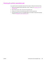
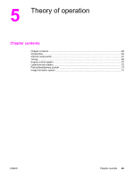
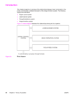
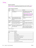
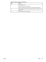
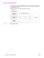
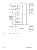
Timing Sequence of operation Operation sequences are controlled by the microprocessor on the dc controller. Table 5-1. Sequence of operation describes engine operations for each period of a print operation. Table 5-1. Sequence of operation Name Timing Purpose WAIT From power-on until the end of the main motor initial drive Detects presence of a print cartridge. Clears potential from the drum surface and cleans the transfer roller. See Table 5-2. Power-on sequence for a complete description of the WAIT (poweron) period. Also see General timing chart for detailed information about printer timing. STBY (standby) From the end of the WAIT or LSTR period until either a print command is sent from the formatter or the power is turned off. Prepares the printer to receive print commands INTR (initial From the time of the print command until Prepares the photosensitive drum for rotation) the pickup solenoid is turned on. printing. PRINT From the end of the INTR period until the primary high-voltage is turned off. Forms the image on the photosensitive drum and transfers the toner image to the media. LSTR (last rotation) From the end of the PRINT period (when high-voltage is turned off) until the main motor stops rotating. Delivers the last page of a print job. After LSTR, the printer either returns to STBY or, if another print command was sent from the formatter, enters INTR. Power-on sequence Table 5-2. Power-on sequence Step Action 1 Power-on 2 CPU initialization 3 Video interface communication start 4 Check sensors for residual media 5 Main motor initial drive 6 Fuser heater initial drive. The fuser heater reaches a surface temperature of 100 degrees C. 7 Laser/scanner motor initial drive 68 Chapter 5 Theory of operation ENWW
-
 1
1 -
2
-
3
-
4
-
5
-
6
-
7
-
8
-
9
-
10
-
11
-
12
-
13
-
14
-
15
-
16
-
17
-
18
-
19
-
20
-
21
-
22
-
23
-
24
-
25
-
26
-
27
-
28
-
29
-
30
-
31
-
32
-
33
-
34
-
35
-
36
-
37
-
38
-
39
-
40
-
41
-
42
-
43
-
44
-
45
-
46
-
47
-
48
-
49
-
50
-
51
-
52
-
53
-
54
-
55
-
56
-
57
-
58
-
59
-
60
-
61
-
62
-
63
-
64
-
65
-
66
-
67
-
68
-
69
-
70
-
71
-
72
-
73
-
74
-
 75
75 -
 76
76 -
 77
77 -
 78
78 -
 79
79 -
 80
80 -
 81
81 -
 82
82 -
 83
83 -
 84
84 -
 85
85 -
86
-
87
-
88
-
89
-
90
-
91
-
92
-
93
-
94
-
95
-
96
-
97
-
98
-
99
-
100
-
101
-
102
-
103
-
104
-
105
-
106
-
107
-
108
-
109
-
110
-
111
-
112
-
113
-
114
-
115
-
116
-
117
-
118
-
119
-
120
-
121
-
122
-
123
-
124
-
125
-
126
-
127
-
128
-
129
-
130
-
131
-
132
-
133
-
134
-
135
-
136
-
137
-
138
-
139
-
140
-
141
-
142
-
143
-
144
-
145
-
146
-
147
-
148
-
149
-
150
-
151
-
152
-
153
-
154
-
155
-
156
-
157
-
158
-
159
-
160
-
161
-
162
-
163
-
164
-
165
-
166
-
167
-
168
-
169
-
170
-
171
-
172
-
173
-
174
-
175
-
176
-
177
-
178
-
179
-
180
-
181
-
182
-
183
-
184
-
185
-
186
-
187
-
188
-
189
-
190
-
191
-
192
-
193
-
194
-
195
-
196
-
197
-
198
-
199
-
200
-
201
-
202
-
203
-
204
-
205
-
206
-
207
-
208
-
209
-
210
-
211
-
212
-
213
-
214
-
215
-
216
-
217
-
218
-
219
-
220
-
221
-
222
-
223
-
224
-
225
-
226
-
227
-
228
-
229
-
230
-
231
-
232
-
233
-
234
-
235
-
236
-
237
-
238
-
239
-
240
-
241
-
242
-
243
-
244
-
245
-
246
-
247
-
248
-
249
-
250
-
251
-
252
-
253
-
254
 |
 |