HP StorageWorks 2/16V Brocade Fabric Watch Administrator's Guide - Supporting - Page 64
Step 2: Implement your switch status policy, Configuring FRUs
 |
View all HP StorageWorks 2/16V manuals
Add to My Manuals
Save this manual to your list of manuals |
Page 64 highlights
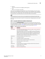
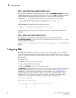
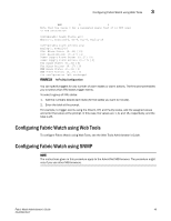
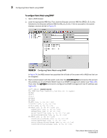
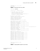
3 Configuring FRUs STEP 2: IMPLEMENT YOUR SWITCH STATUS POLICY After planning and defining your switch status policy, enter the switchStatusPolicySet command to configure each policy. Each policy has two parameters that can be configured: Marginal and Down. Set the number of units Marginal or Down based on your system requirements for each policy/parameter. The following example shows a switch status policy for Temperature: Bad Temperatures contributing to DOWN status: (0..10) [0] 3 Bad Temperatures contributing to MARGINAL status: (0..10) [0] 1 The following example shows a switch status policy for Fans: Bad Fans contributing to DOWN status: (0..3) [0] 2 Bad Fans contributing to MARGINAL status: (0..3) [0] 1 Switch status policies are saved in a non volatile memory, and therefore are persistent until changed. STEP 3: VIEW YOUR SWITCH STATUS POLICY After defining and configuring your switch status policy, you can view them using the switchStatusPolicyShow command. Note that the policy you defined here determines the output in the Switch Status Policy Report. See Chapter 4, "Generating Fabric Watch Reports" for more details about the Switch Status Policy Report. Configuring FRUs The configuration of FRUs is an exception to the procedures described thus far in this chapter. FRUs are monitored using state values, as opposed to the quantitative values used to monitor the rest of the fabric. As a result of the qualitative nature of this monitoring, the concept of thresholds does not apply. To configure FRUs: 1. Establish a telnet connection with a switch. 2. Log in using administrative privileges. 3. Enter the fwFruCfg command at the command prompt. The fwFruCfg command displays your current FRU configuration, as shown in Figure 23. The types of FRUs are different for the various platforms. In the prompt that follows your current FRU configuration, you are asked to provide values for each FRU alarm state and alarm action. To accept the default value for each FRU (as shown in Figure 23), press Return. After you have configured a FRU alarm state and alarm action, the values apply to all FRUs of that type. For example, the values specified for a slot FRU will apply to all slots in the enclosure. swd123:admin> fwfrucfg The current FRU configuration: Alarm State Alarm Action Slot 31 1 Power Supply 0 0 Fan 0 0 48 Fabric Watch Administrator's Guide 53-0000438-01
-
 1
1 -
2
-
3
-
4
-
5
-
6
-
7
-
8
-
9
-
10
-
11
-
12
-
13
-
14
-
15
-
16
-
17
-
18
-
19
-
20
-
21
-
22
-
23
-
24
-
25
-
26
-
27
-
28
-
29
-
30
-
31
-
32
-
33
-
34
-
35
-
36
-
37
-
38
-
39
-
40
-
41
-
42
-
43
-
44
-
45
-
46
-
47
-
48
-
49
-
50
-
51
-
52
-
53
-
54
-
55
-
56
-
57
-
58
-
 59
59 -
 60
60 -
 61
61 -
 62
62 -
 63
63 -
 64
64 -
 65
65 -
 66
66 -
 67
67 -
 68
68 -
 69
69 -
70
-
71
-
72
-
73
-
74
-
75
-
76
-
77
-
78
-
79
-
80
-
81
-
82
-
83
-
84
-
85
-
86
-
87
-
88
-
89
-
90
-
91
-
92
-
93
-
94
-
95
-
96
-
97
-
98
-
99
-
100
-
101
-
102
 |
 |