Panasonic AJ-HPM200 Operating Instructions - Page 20
AUDIO REC VOL SEL switch, INPUT SELECT buttons
 |
View all Panasonic AJ-HPM200 manuals
Add to My Manuals
Save this manual to your list of manuals |
Page 20 highlights
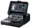
4. METER SELECT switch Switches to CH1-4 or CH5-8 in the audio meter and the monitor. 5. INPUT SELECT buttons Switch between video and audio input signals. VIDEO: AUDIO: Press the VIDEO button to open a screen for selecting input signal. Pressing the button when the screen is open enables selection of CMPST, HDSDI, SDSDI, 1394 or SG input. When SG is selected, the signal switches to the internal signal selected in setup menu No. 601 (VIDEO INT SG). Selecting composite or SD SDI when setup menu No. 020 (SYS FORMAT) is set to 1080i or 720p automatically up-converts SD to HD when recording. The unit indicates this as CMPST (U/C) and SDSDI (U/C). Press the AUDIO button to open a screen for selecting input signal. Pressing the button when the screen is open enables selection of ANALOG, AES/EBU, SDI or SG input. ◆ NOTE: • When VIDEO is set to 1394, AUDIO is automatically set to 1394. • The selected input item blinks when there is no input signal. • Press the INPUT SELECT button once to show the current setting. When you do not want to change the setting, press the EXIT button or wait for 3 seconds to allow the display of the current setting to vanish. 6. AUDIO REC VOL SEL switch UNITY/VAR switch UNITY: VAR: Records the audio signals at a fixed level regardless of the positions of the audio level controls. Records audio signals at the level set with the audio level controls. Audio level controls Use these controls to adjust the recording levels of the audio signals (CH1/CH2/CH3/CH4). However, the recording level cannot be adjusted during 1394 input. 8. Search dial Use to search and check video. ➝Refer to "Jog and Shuttle Operations Using the Search Dial" (page 44). Hold down the SHIFT button and turn the search dial to perform high-speed scrolling in the thumbnail screen. ➝Refer to "Thumbnail and Clip Management" (page 46). 9. Audio playback level controls Adjust the playback level of audio signals (of channels selected using the UNITY/VAR channel select switch). However, they cannot adjust the playback level of 1394 output signals. CH5 to 8 are at all times played back at a fixed level. 10.UNITY/VAR channel select switches UNITY: 1(2): 1+3 (2+4): 3(4): Plays back audio signals at a fixed level regardless of the positions of the audio level controls. Plays back and outputs audio CH1(2) at the level adjusted using the audio level controls to CH1(2) and at a fixed level to CH3(4). Plays back and outputs audio CH1(2) and CH3(4) at the level adjusted using the audio level controls to CH1(2) and CH3(4). Plays back and outputs audio CH3(4) at the level adjusted using the audio level controls to CH3(4) and at a fixed level to CH1(2). 11.MODE button Switch to the USB device mode for connecting a personal computer, to the network server mode, browser mode or AVCHD mode (available only with optional equipment). Press this button to open the mode selection screen on the LCD monitor and select the desired mode. ➝For details, refer to "Using USB or eSATA Connectors" (page 112). ➝Refer to "Connecting This Unit to a Network" (page 126). ➝Refer to "Operating the AVCHD Thumbnail Screens" (page 143). 7. POWER indicator Lights when the power is on. 20 Introduction: Control Reference Guide
-
 1
1 -
2
-
3
-
4
-
5
-
6
-
7
-
8
-
9
-
10
-
11
-
12
-
13
-
14
-
 15
15 -
 16
16 -
 17
17 -
 18
18 -
 19
19 -
 20
20 -
 21
21 -
 22
22 -
 23
23 -
 24
24 -
 25
25 -
26
-
27
-
28
-
29
-
30
-
31
-
32
-
33
-
34
-
35
-
36
-
37
-
38
-
39
-
40
-
41
-
42
-
43
-
44
-
45
-
46
-
47
-
48
-
49
-
50
-
51
-
52
-
53
-
54
-
55
-
56
-
57
-
58
-
59
-
60
-
61
-
62
-
63
-
64
-
65
-
66
-
67
-
68
-
69
-
70
-
71
-
72
-
73
-
74
-
75
-
76
-
77
-
78
-
79
-
80
-
81
-
82
-
83
-
84
-
85
-
86
-
87
-
88
-
89
-
90
-
91
-
92
-
93
-
94
-
95
-
96
-
97
-
98
-
99
-
100
-
101
-
102
-
103
-
104
-
105
-
106
-
107
-
108
-
109
-
110
-
111
-
112
-
113
-
114
-
115
-
116
-
117
-
118
-
119
-
120
-
121
-
122
-
123
-
124
-
125
-
126
-
127
-
128
-
129
-
130
-
131
-
132
-
133
-
134
-
135
-
136
-
137
-
138
-
139
-
140
-
141
-
142
-
143
-
144
-
145
-
146
-
147
-
148
-
149
-
150
-
151
-
152
-
153
-
154
-
155
-
156
-
157
-
158
-
159
-
160
-
161
-
162
-
163
-
164
-
165
-
166
-
167
-
168
-
169
-
170
-
171
-
172
-
173
-
174
-
175
-
176
-
177
-
178
-
179
-
180
-
181
-
182
-
183
-
184
-
185
-
186
-
187
-
188
-
189
-
190
-
191
-
192
-
193
-
194
-
195
-
196
-
197
-
198
-
199
-
200
-
201
-
202
-
203
-
204
-
205
-
206
-
207
-
208
-
209
-
210
-
211
-
212
-
213
-
214
-
215
-
216
-
217
-
218
 |
 |
