Canon EOS C300 Mark III EOS C300 Mark III EOS C500 Mark II Instruction Manual - Page 16
Electronic Viewfinder, EU-V1 Expansion Unit 1 or, INPUT terminals XLR: INPUT 1 top, INPUT 2
 |
View all Canon EOS C300 Mark III manuals
Add to My Manuals
Save this manual to your list of manuals |
Page 16 highlights
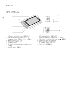
Names of Parts 16 1 2 13 10 11 14 3 4 15 12 5 16 6 7 17 8 18 19 9 20 1 Expansion unit connector For connecting the optional EVF-V50 OLED Electronic Viewfinder, EU-V1 Expansion Unit 1 or EU-V2 Expansion Unit 2. 2 Expansion unit connector cover 3 Power indicator/Rear tally lamp (A 51) 4 FUNC (main functions) button (A 67)/ Assignable button Camera 12 (A 121) 5 Joystick (A 34) 6 CANCEL button (A 34) 7 MENU button (A 34, 121) 8 Screw holes for M4 bolts (7.5 mm (0.30 in.) deep, x4) 9 Battery compartment (A 26) 10 MON. terminal (A 145, 146) 11 SDI OUT terminal (A 145) 12 TIME CODE terminal (A 97, 98) 13 REMOTE A terminal (A 120) For connecting the optional RC-V100 Remote Controller or commercially available remote controllers. 14 HDMI OUT terminal (A 145, 146) 15 MIC (microphone) terminal (A 103) 16 × (headphone) terminal (A 107) 17 INPUT terminals (XLR): INPUT 1 (top), INPUT 2 (bottom) (A 103) 18 AUDIO STATUS (display the [¡ Audio Setup] status screens) button (A 200)/ Assignable button Camera 13 (A 121) 19 DC IN 12V terminal (A 27) 20 BATTERY RELEASE button (A 26) Removing and attaching the terminal covers You can remove the covers of the camera's terminals to access them more easily. To remove a terminal's cover, open the cover and gently pull it straight out. To attach back the terminal cover, insert the connecting strip into the opening. NOTES • If the connecting strip is difficult to grasp, use a pair of tweezers or similar tool.
-
 1
1 -
2
-
3
-
4
-
5
-
6
-
7
-
8
-
9
-
10
-
 11
11 -
 12
12 -
 13
13 -
 14
14 -
 15
15 -
 16
16 -
 17
17 -
 18
18 -
 19
19 -
 20
20 -
 21
21 -
22
-
23
-
24
-
25
-
26
-
27
-
28
-
29
-
30
-
31
-
32
-
33
-
34
-
35
-
36
-
37
-
38
-
39
-
40
-
41
-
42
-
43
-
44
-
45
-
46
-
47
-
48
-
49
-
50
-
51
-
52
-
53
-
54
-
55
-
56
-
57
-
58
-
59
-
60
-
61
-
62
-
63
-
64
-
65
-
66
-
67
-
68
-
69
-
70
-
71
-
72
-
73
-
74
-
75
-
76
-
77
-
78
-
79
-
80
-
81
-
82
-
83
-
84
-
85
-
86
-
87
-
88
-
89
-
90
-
91
-
92
-
93
-
94
-
95
-
96
-
97
-
98
-
99
-
100
-
101
-
102
-
103
-
104
-
105
-
106
-
107
-
108
-
109
-
110
-
111
-
112
-
113
-
114
-
115
-
116
-
117
-
118
-
119
-
120
-
121
-
122
-
123
-
124
-
125
-
126
-
127
-
128
-
129
-
130
-
131
-
132
-
133
-
134
-
135
-
136
-
137
-
138
-
139
-
140
-
141
-
142
-
143
-
144
-
145
-
146
-
147
-
148
-
149
-
150
-
151
-
152
-
153
-
154
-
155
-
156
-
157
-
158
-
159
-
160
-
161
-
162
-
163
-
164
-
165
-
166
-
167
-
168
-
169
-
170
-
171
-
172
-
173
-
174
-
175
-
176
-
177
-
178
-
179
-
180
-
181
-
182
-
183
-
184
-
185
-
186
-
187
-
188
-
189
-
190
-
191
-
192
-
193
-
194
-
195
-
196
-
197
-
198
-
199
-
200
-
201
-
202
-
203
-
204
-
205
-
206
-
207
-
208
-
209
-
210
-
211
-
212
-
213
-
214
-
215
-
216
-
217
-
218
-
219
-
220
-
221
-
222
-
223
-
224
-
225
-
226
-
227
-
228
-
229
-
230
-
231
-
232
-
233
-
234
-
235
-
236
-
237
-
238
-
239
-
240
-
241
-
242
-
243
-
244
-
245
-
246
-
247
 |
 |
